
Implementing Aggregate VLAN on Huawei Switches
- May 19, 2024
- Posted by: James Majani
- Categories: Huawei, Networking
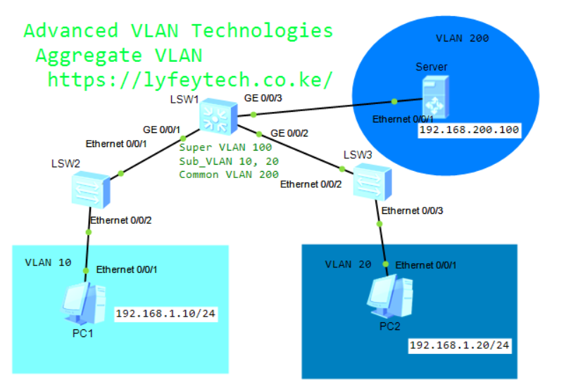
VLAN aggregation, also called super-VLAN, partitions broadcast domain into multiple VLANs (sub-VLANs) on a physical network and aggregates the sub-VLANs into a single logical VLAN (super-VLAN). The sub-VLANs use the same IP subnet and default gateway address, so the number of IP addresses used is reduced.
Step 1: Create super-VLAN and sub-VLANs. Configure VLAN 10 and VLAN 20 as sub-VLANs of VLAN 100.
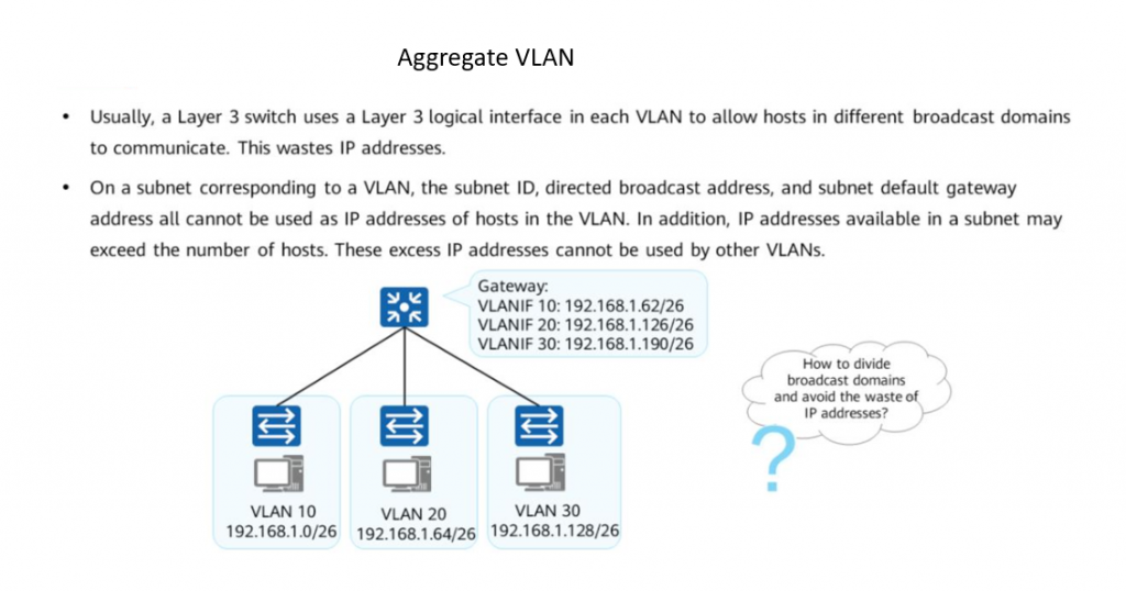
•Sub-VLAN: contains only physical interfaces, and is used to isolate broadcast domains. A sub-VLAN cannot be used to create a Layer 3 VLANIF interface.
Hosts in each sub-VLAN use the VLANIF interface of its super-VLAN to communicate with external devices at Layer 3.
• Super-VLAN: A super-VLAN contains only Layer 3 VLANIF interfaces and does not contain physical interfaces. A super-VLAN corresponds to a subnet gateway, Different from a common VLAN, the VLANIF interface status of a super-VLAN depends on the physical interface status of the sub-VLANs in the super-VLAN.
*******************************************LSW1
system-view
sysname LSW1
vlan batch 10 20
interface GigabitEthernet 0/0/1
port link-type trunk
port trunk allow-pass vlan 10
#
interface GigabitEthernet 0/0/2
port link-type trunk
port trunk allow-pass vlan 20
#
vlan 100
aggregate-vlan
access-vlan 10 20
#
interface vlanif 100
ip address 192.168.1.1 24
#
vlan 200
quit
interface GigabitEthernet 0/0/3
port link-type access
port default vlan 200
#
interface vlanif 200
ip address 192.168.200.1 24
Step 2: Configure VLANs on interfaces of Access Switches.
*******************************************LSW2
ystem-view
sysname LSW2

vlan 10
quit
interface Ethernet 0/0/1
port link-type trunk
port trunk allow-pass vlan 10
quit
interface Ethernet 0/0/2
port link-type access
port default vlan 10

*******************************************LSW3
system-view
sysname LSW3
vlan 20
quit
interface Ethernet 0/0/2
port link-type trunk
port trunk allow-pass vlan 20
quit
interface Ethernet 0/0/3
port link-type access
port default vlan 20
Step 3 : Result verification.
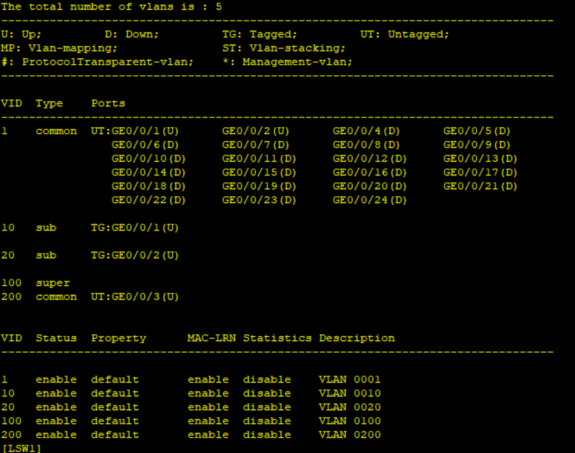
Run the command Display Vlan on LSW1
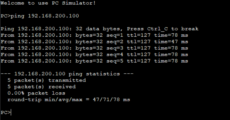
Ping the Server from a Host.
The communication between LSW1 configured with VLAN aggregation and other devices is similar to normal Layer 2 communication without the super-VLAN. When a PC in a sub-VLAN needs to communicate with other networks at Layer 3, the PC sends data to the default gateway, that is, the VLANIF interface corresponding to the super-VLAN, and then routes the data.
Test communication between Host in different sub-VLANs.
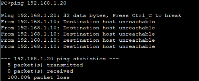
When hosts in different sub-VLANs communicate with each other, the hosts send ARP Request packets because IP addresses of the sub-VLANs belong to the same network segment. Actually, different sub-VLANs belong to different broadcast domains. As a result, ARP packets cannot be transmitted to other sub-VLANs, there is no response to ARP Request packets, and the device cannot learn the MAC address of the peer end. As a result, sub-VLANs cannot communicate with each other. To implement communication between sub-VLANs, enable proxy ARP on the VLANIF interface of the super-VLAN.
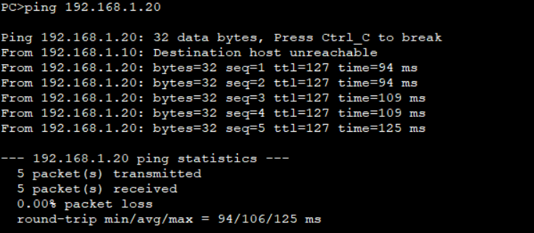
Step 4: Enable proxy ARP on the super-VLAN on LSW1 and Ping PC2 from PC1.
*******************************************LSW1
interface vlanif 100
arp-proxy inter-sub-vlan-proxy enable
Thanks for the great article, still unable to ping PC2 from PC1 even after enabling proxy ARP in LSW1 on VLANIF 100 below are the PC configurations can you please guide
PC1: IP Address 192.168.1.10 24
GW: 192.168.1.1
PC2 IP Address 192.168.1.20 24
GW: 192.168.1.1
Hello, ensure that you have allowed necessary VLANs to pass through downlinks of LSW1 and the uplinks of LSW2 & LSW3. Also double confirm the access VLANs are configured correctly. If it still doesn’t work, share a teams/google meeting we troubleshoot together.
Thanks a lot for your feedback, I revisited the configurations in all switches and found one mistake. Now its pingable after correction
thailand pharmacy viagra: Pharm Express 24 – roman online pharmacy reviews
can i buy viagra over the counter in south africa VGR Sources how to buy generic viagra in canada
viagra 500mg online: sildenafil mexico – cheap brand viagra 100mg
viagra 1000mg: VGR Sources – where to buy generic viagra over the counter
sildenafil 25 mg india: VGR Sources – generic viagra from mexico
sildenafil nz cost: sildenafil prescription australia – sildenafil medication cost
sildenafil 20 mg coupon VGR Sources best price for sildenafil 100 mg
online pharmacy viagra 100mg: VGR Sources – generic viagra india price
online generic viagra india: VGR Sources – where can i buy generic viagra in usa
https://vgrsources.com/# viagra soft tabs uk
viagra 500mg price: cheap generic viagra fast delivery – buy sildenafil pills
sildenafil prescription discount canada generic viagra price sildenafil cost india