
VXLAN (intra-subnet communication) Implementation on Huawei switches.
- September 15, 2024
- Posted by: James Majani
- Categories: Huawei, Networking
Virtual extensible Local-Area Network (VXLAN) is a network virtualization technology standard. It caters to the limitations of the VLAN, enhancing scalability, performance, security, and network virtualization through isolated segmentation in cloud environments. VXLANs overcome VLAN scaling limitations in the following ways:
1) You can theoretically create as many as 16 million VXLANs in an administrative domain, compared to a maximum of 4094 traditional VLANs. In this way, VXLANs provide network segmentation at the scale required by cloud and service providers to support very large numbers of tenants.
2) VXLANs enable you to create network segments that stretch between data centers. Traditional VLAN-based network segmentation creates broadcast domains, but as soon as a packet containing VLAN tags hits a router, all of that VLAN information is removed. This means VLANs only travel as far as your underlying Layer 2 network can reach. This is a problem for some use cases, such as virtual machine (VM) migration, which typically prefers not to cross Layer 3 boundaries. By contrast, VXLAN network segmentation encapsulates the original packet inside a UDP packet. This allows a VXLAN network segment to extend as far as the physical Layer 3 routed network can reach, provided that all switches and routers in the path support VXLAN, without the applications running on the virtual overlay network being required to cross any Layer 3 boundaries. As far as the servers connected to the network are concerned, they are part of the same Layer 2 network, even though the underlying UDP packets may have transited one or more routers.
3) The ability to provide Layer 2 segmentation over the top of an underlying Layer 3 network, combined with the high number of supported network segments, allows servers to be part of the same VXLAN even if they are remote from one another while enabling network administrators to keep Layer 2 networks small. Having smaller Layer 2 networks helps avoid MAC table overflow on switches.
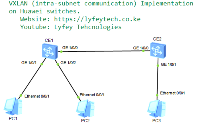
Networking Description.
Configure a VXLAN tunnel between the two switches to enable the three PCs on the same network segment to communicate with each other.
Step 1: Basic configurations.
*******************************************CE1
sysname CE1
#
#
interface GE1/0/0
 undo portswitch
 undo shutdown
 ip address 10.1.0.1 255.255.255.252
#
interface LoopBack0
 description VTEP
 ip address 10.0.0.1 255.255.255.255
#
interface LoopBack1
 description ROUTER-ID
 ip address 1.1.1.1 255.255.255.255

*******************************************CE2
sysname CE2
#
interface GE1/0/0
 undo portswitch
 undo shutdown
 ip address 10.1.0.2 255.255.255.252
#
interface LoopBack0
 description VTEP
 ip address 10.0.0.2 255.255.255.255
#
interface LoopBack1
 description ROUTER-ID
 ip address 2.2.2.2 255.255.255.255
Step 2: Configure OSPF between the two switches.
*******************************************CE1
ospf 1 router-id 1.1.1.1
 area 0.0.0.0
  network 10.0.0.1 0.0.0.0
  network 10.1.0.0 0.0.0.3

*******************************************CE2
ospf 1 router-id 2.2.2.2
 area 0.0.0.0
  network 10.0.0.2 0.0.0.0
  network 10.1.0.0 0.0.0.3
Step 3: Configure BD, VNI, VTEPs and VAPs .
*******************************************CE1
bridge-domain 10
 vxlan vni 100
#
interface Nve1
 source 10.0.0.1
 vni 100 head-end peer-list 10.0.0.2
#
interface GE1/0/1
 undo shutdown
#
interface GE1/0/1.1 mode l2
 encapsulation untag
 bridge-domain 10
#
interface GE1/0/2
 undo shutdown
#
interface GE1/0/2.1 mode l2
 encapsulation untag
 bridge-domain 10

*******************************************CE2
bridge-domain 10
 vxlan vni 100
#
interface Nve1
 source 10.0.0.2
 vni 100 head-end peer-list 10.0.0.1
#
interface GE1/0/1
 undo shutdown
#
interface GE1/0/1.1 mode l2
 encapsulation untag
 bridge-domain 10
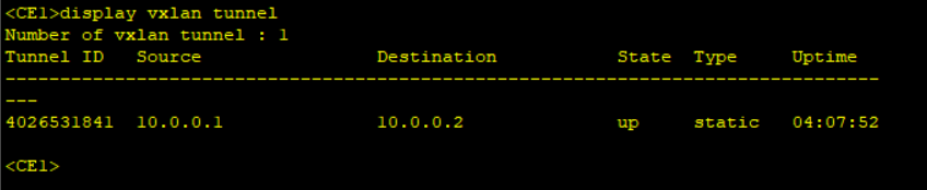
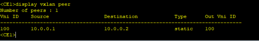
In static mode, there is no control plane. During VXLAN tunnel establishment, you need to manually specify the IP addresses of the local VTEP and remote VTEP as the VXLAN tunnel’s source and destination IP addresses, respectively. The static mode has poor flexibility and requires a lot of manual configuration, it is not applicable to large-scale networking scenarios.
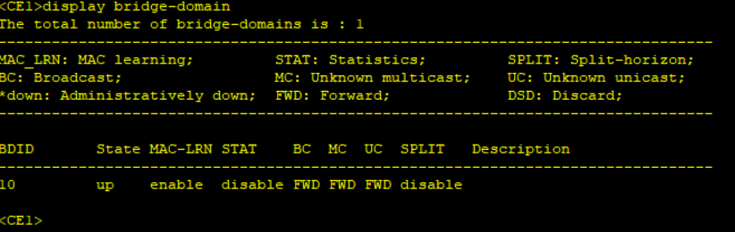
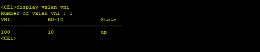
Step 4: Results confirmation.
Leave a Reply
You must be logged in to post a comment.