
Using BGP attributes to control traffic flow among ASes-A real networking case on Huawei Routers
- March 9, 2024
- Posted by: Lyfey Technologies
- Category: Networking
BGP has many attributes which are considered during route selection. These attributes can be used to control traffic flow into and out of an AS. This lab simulates a real networking case of how BGP attributes can be applied to control traffic flow between ASes.
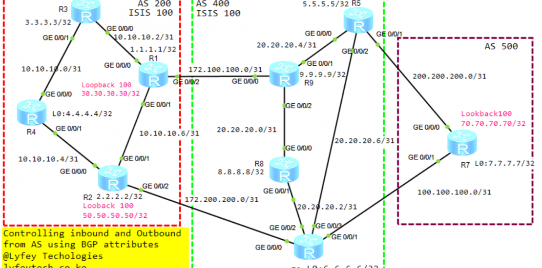
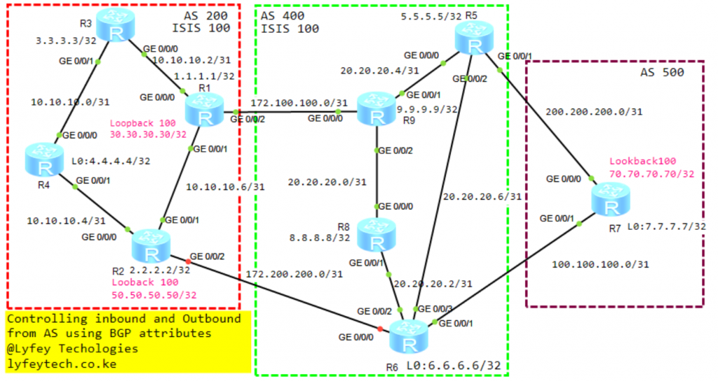
Topology Diagram
Lab Objective and Issue Description.
We have three Ases 200,400 and 500. R1 and R2 are ASGs in AS 200. R3 and R4 and RSGs and the RRs in AS 200. R9 and R8 are ASGs in AS 400 while R5 and R6 are the RSGs and the RRs in AS 400. The RSGs in AS 400 R5 and R6 are dual-homed to R7 in AS 500 connected to the internet. In the existing network, we only had one connection between As 200 and AS 400, that’s the connection between R1 GE 0/0/2 and R9 GE 0/0/0 with a capacity of 50G. To ensure reliability, we introduced another connection between AS 200 and AS 400, that’s the connection between R2 GE 0/0/2 and R6 GE 0/0/0 which is 20G and should purely be a protection link. All traffic between As 200 and AS 400 should continue to flow using the primary path between R1 and R9. The traffic should be able to switch to the secondary path between R2 and R6 when we lose the primary path.
Configurations in the existing network
****************************R1
sysname R1
mpls lsr-id 1.1.1.1
mpls
#
mpls ldp
#
isis 100
 is-level level-2
 cost-style wide
 network-entity 49.0100.0001.0001.0001.00
#
interface GigabitEthernet0/0/0
 description TO_R3_GE 0/0/0
 ip address 10.10.10.2 255.255.255.254
 isis enable 100
 mpls
 mpls ldp
#
interface GigabitEthernet0/0/1
 description TO_R2_GE 0/0/1
 ip address 10.10.10.6 255.255.255.254
 isis enable 100
 mpls
 mpls ldp
#
interface GigabitEthernet0/0/2
 description TO_R9_GE 0/0/0
 ip address 172.100.100.0 255.255.255.254
#
interface LoopBack0
 ip address 1.1.1.1 255.255.255.255
 isis enable 100
#
#
interface LoopBack100
 ip address 30.30.30.30 255.255.255.255
#
bgp 200
 peer 3.3.3.3 as-number 200
 peer 3.3.3.3 connect-interface LoopBack0
 peer 4.4.4.4 as-number 200
 peer 4.4.4.4 connect-interface LoopBack0
 peer 172.100.100.1 as-number 400
 #
 ipv4-family unicast
  undo synchronization
  import-route direct
  peer 3.3.3.3 enable
  peer 4.4.4.4 enable
  peer 172.100.100.1 enable
#
commit
**********************************R2
sysname R2
#
mpls lsr-id 2.2.2.2
mpls
#
mpls ldp
#
isis 100
is-level level-2
cost-style wide
network-entity 49.0100.0002.2002.0002.00
#
interface GigabitEthernet0/0/0
description TO_R4_GE 0/0/0
ip address 10.10.10.4 255.255.255.254
isis enable 100
mpls
mpls ldp
#
interface GigabitEthernet0/0/1
description TO_R1_GE 0/0/1
ip address 10.10.10.7 255.255.255.254
isis enable 100
mpls
mpls ldp
#
interface LoopBack0
ip address 2.2.2.2 255.255.255.255
isis enable 100
#
interface LoopBack100
ip address 50.50.50.50 255.255.255.255
#
bgp 200
router-id 2.2.2.2
peer 3.3.3.3 as-number 200
peer 3.3.3.3 connect-interface LoopBack0
peer 4.4.4.4 as-number 200
peer 4.4.4.4 connect-interface LoopBack0
#
ipv4-family unicast
undo synchronization
import-route direct
peer 3.3.3.3 enable
peer 4.4.4.4 enable
#
commit******************************R3
sysname R3
#
mpls lsr-id 3.3.3.3
mpls
#
mpls ldp
#
isis 100
is-level level-2
cost-style wide
network-entity 49.0100.0003.3003.0003.00
#
interface GigabitEthernet0/0/0
description TO_R1_GE 0/0/0
ip address 10.10.10.3 255.255.255.254
isis enable 100
mpls
mpls ldp
#
interface GigabitEthernet0/0/1
description TO_R4_GE 0/0/0
ip address 10.10.10.0 255.255.255.254
isis enable 100
mpls
mpls ldp
#
interface LoopBack0
ip address 3.3.3.3 255.255.255.255
isis enable 100
#
bgp 200
router-id 3.3.3.3
peer 1.1.1.1 as-number 200
peer 1.1.1.1 connect-interface LoopBack0
peer 2.2.2.2 as-number 200
peer 2.2.2.2 connect-interface LoopBack0
peer 3.3.3.3 as-number 200
peer 3.3.3.3 connect-interface LoopBack0
peer 4.4.4.4 as-number 200
peer 4.4.4.4 connect-interface LoopBack0
#
ipv4-family unicast
undo synchronization
reflector cluster-id 3.3.3.3
peer 1.1.1.1 enable
peer 1.1.1.1 reflect-client
peer 2.2.2.2 enable
peer 2.2.2.2 reflect-client
peer 3.3.3.3 enable
peer 4.4.4.4 enable
#
commit*******************************R4
sysname R4
#
mpls lsr-id 4.4.4.4
mpls
#
mpls ldp
#
isis 100
is-level level-2
cost-style wide
network-entity 49.0100.0004.4004.0004.00
#
interface GigabitEthernet0/0/0
description TO_R3_GE 0/0/1
ip address 10.10.10.1 255.255.255.254
isis enable 100
mpls
mpls ldp
#
interface GigabitEthernet0/0/1
description TO_R2_GE 0/0/0
ip address 10.10.10.5 255.255.255.254
isis enable 100
mpls
mpls ldp
#
interface LoopBack0
ip address 4.4.4.4 255.255.255.255
isis enable 100
#
bgp 200
router-id 4.4.4.4
peer 1.1.1.1 as-number 200
peer 1.1.1.1 connect-interface LoopBack0
peer 2.2.2.2 as-number 200
peer 2.2.2.2 connect-interface LoopBack0
peer 3.3.3.3 as-number 200
peer 3.3.3.3 connect-interface LoopBack0
#
ipv4-family unicast
undo synchronization
reflector cluster-id 4.4.4.4
peer 1.1.1.1 enable
peer 1.1.1.1 reflect-client
peer 2.2.2.2 enable
peer 2.2.2.2 reflect-client
peer 3.3.3.3 enable
#
commit*********************************R5
sysname R5
#
mpls lsr-id 5.5.5.5
mpls
#
mpls ldp
#
isis 100
is-level level-2
cost-style wide
network-entity 49.0100.0005.5005.0005.00
#
interface GigabitEthernet0/0/0
description TO_R9_GE 0/0/1
ip address 20.20.20.5 255.255.255.254
isis enable 100
mpls
mpls ldp
#
interface GigabitEthernet0/0/1
description TO_R7_GE 0/0/0
ip address 200.200.200.0 255.255.255.254
mpls
mpls ldp
#
interface GigabitEthernet0/0/2
description TO_R6_GE 0/0/3
ip address 20.20.20.6 255.255.255.254
isis enable 100
mpls
mpls ldp
#
interface LoopBack0
ip address 5.5.5.5 255.255.255.255
isis enable 100
#
bgp 400
router-id 5.5.5.5
peer 6.6.6.6 as-number 400
peer 6.6.6.6 connect-interface LoopBack0
peer 8.8.8.8 as-number 400
peer 8.8.8.8 connect-interface LoopBack0
peer 9.9.9.9 as-number 400
peer 9.9.9.9 connect-interface LoopBack0
peer 200.200.200.1 as-number 500
#
ipv4-family unicast
undo synchronization
reflector cluster-id 5.5.5.5
import-route direct
peer 6.6.6.6 enable
peer 6.6.6.6 reflect-client
peer 8.8.8.8 enable
peer 9.9.9.9 enable
peer 9.9.9.9 reflect-client
peer 200.200.200.1 enable
#
commit*********************************R6
#
sysname R6
#
mpls lsr-id 6.6.6.6
mpls
#
mpls ldp
#
isis 100
is-level level-2
cost-style wide
network-entity 49.0100.0006.6006.0006.00
#
interface GigabitEthernet0/0/0
description TO_R2_GE 0/0/2
ip address 172.200.200.1 255.255.255.254
mpls
mpls ldp
#
interface GigabitEthernet0/0/1
description TO_R7_GE 0/0/1
ip address 100.100.100.0 255.255.255.254
mpls
mpls ldp
#
interface GigabitEthernet0/0/2
description TO_R6_GE 0/0/1
ip address 20.20.20.2 255.255.255.254
isis enable 100
mpls
mpls ldp
#
interface GigabitEthernet0/0/3
description TO_R5_GE 0/0/2
ip address 20.20.20.7 255.255.255.254
isis enable 100
mpls
mpls ldp
#
interface LoopBack0
ip address 6.6.6.6 255.255.255.255
isis enable 100
#
bgp 400
router-id 6.6.6.6
peer 5.5.5.5 as-number 400
peer 8.8.8.8 as-number 400
peer 8.8.8.8 connect-interface LoopBack0
peer 9.9.9.9 as-number 400
peer 9.9.9.9 connect-interface LoopBack0
peer 100.100.100.1 as-number 500
peer 172.200.200.0 as-number 200
#
ipv4-family unicast
undo synchronization
reflector cluster-id 6.6.6.6
peer 5.5.5.5 enable
peer 5.5.5.5 next-hop-local
peer 8.8.8.8 enable
peer 8.8.8.8 next-hop-local
peer 9.9.9.9 enable
peer 9.9.9.9 next-hop-local
peer 100.100.100.1 enable
peer 172.200.200.0 enable
#*****************************************R7
#
sysname R7
#
mpls lsr-id 7.7.7.7
mpls
#
mpls ldp
#
interface GigabitEthernet0/0/0
description TO_R5_GE 0/0/1
ip address 200.200.200.1 255.255.255.254
#
interface GigabitEthernet0/0/1
description TO_R6_GE 0/0/1
ip address 100.100.100.1 255.255.255.254
#
interface LoopBack0
ip address 7.7.7.7 255.255.255.255
#
interface LoopBack100
ip address 70.70.70.70 255.255.255.255
#
bgp 500
router-id 7.7.7.7
peer 100.100.100.0 as-number 400
peer 200.200.200.0 as-number 400
#
ipv4-family unicast
undo synchronization
import-route direct
peer 100.100.100.0 enable
peer 200.200.200.0 enable
#
commit*************************************R8
sysname R8
#
mpls lsr-id 8.8.8.8
mpls
#
mpls ldp
#
isis 100
is-level level-2
cost-style wide
network-entity 49.0100.0008.8008.0008.00
#
interface GigabitEthernet0/0/0
description TO_R9_GE 0/0/2
ip address 20.20.20.1 255.255.255.254
isis enable 100
mpls
mpls ldp
#
interface GigabitEthernet0/0/1
description TO_R6_GE 0/0/2
ip address 20.20.20.3 255.255.255.254
isis enable 100
mpls
mpls ldp
#
interface LoopBack0
ip address 8.8.8.8 255.255.255.255
isis enable 100
#
bgp 400
router-id 8.8.8.8
peer 5.5.5.5 as-number 400
peer 5.5.5.5 connect-interface LoopBack0
peer 6.6.6.6 as-number 400
peer 6.6.6.6 connect-interface LoopBack0
#
ipv4-family unicast
undo synchronization
peer 5.5.5.5 enable
peer 6.6.6.6 enable
#
commit*********************************R9
sysname R9
#
mpls lsr-id 9.9.9.9
mpls
#
mpls ldp
#
isis 100
is-level level-2
cost-style wide
network-entity 49.0100.0009.9009.0009.00
#
interface GigabitEthernet0/0/0
description TO_R1_GE 0/0/2
ip address 172.100.100.1 255.255.255.254
#
interface GigabitEthernet0/0/1
description TO_R5_GE 0/0/0
ip address 20.20.20.4 255.255.255.254
isis enable 100
mpls
mpls ldp
#
interface GigabitEthernet0/0/2
description TO_R8_GE 0/0/0
ip address 20.20.20.0 255.255.255.254
isis enable 100
mpls
mpls ldp
#
interface LoopBack0
ip address 9.9.9.9 255.255.255.255
isis enable 100
#
bgp 400
router-id 9.9.9.9
peer 5.5.5.5 as-number 400
peer 5.5.5.5 connect-interface LoopBack0
peer 6.6.6.6 as-number 400
peer 6.6.6.6 connect-interface LoopBack0
peer 172.100.100.0 as-number 200
#
ipv4-family unicast
undo synchronization
peer 5.5.5.5 enable
peer 5.5.5.5 next-hop-local
peer 6.6.6.6 enable
peer 172.100.100.0 enable
#
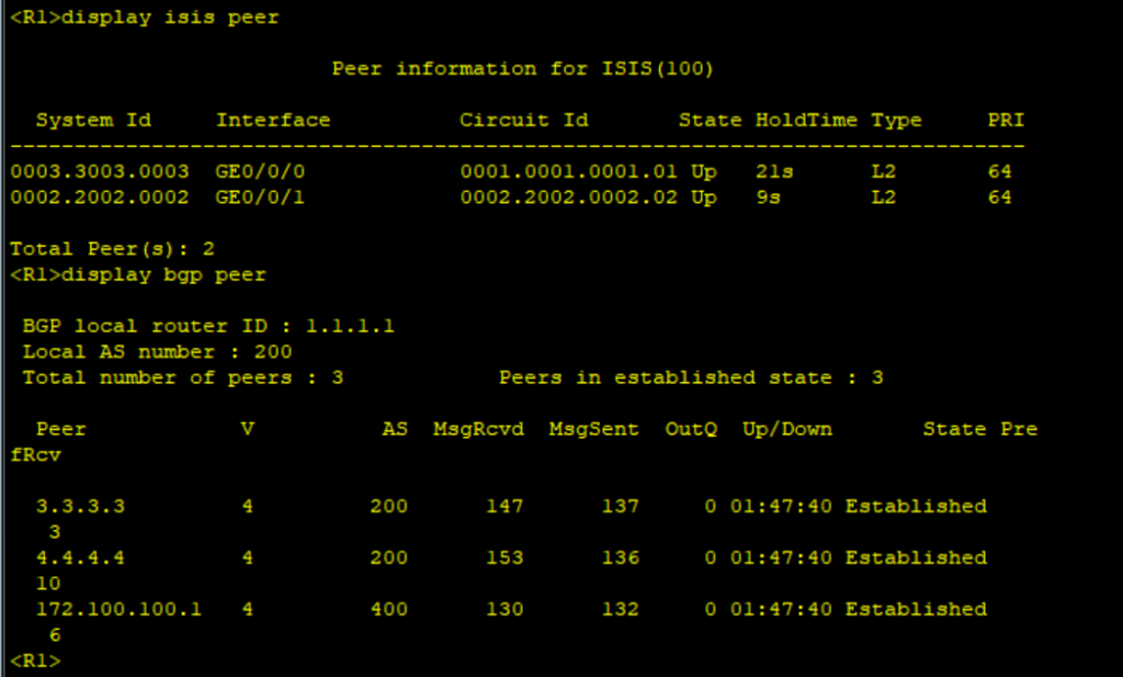
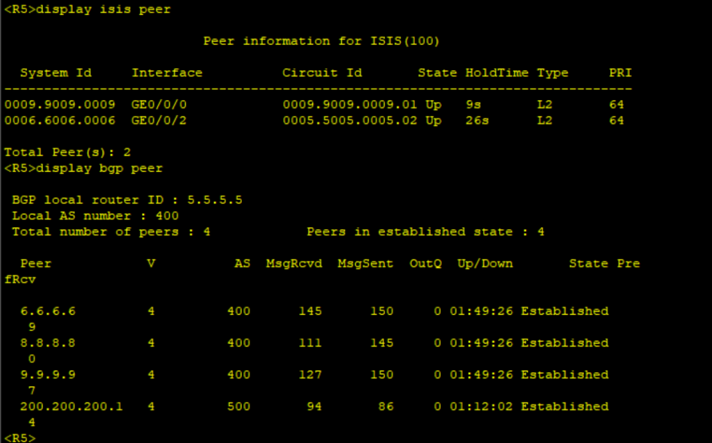
commitVerification of protocol status and traffic flow in the existing network.
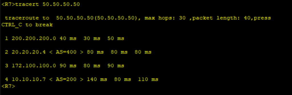
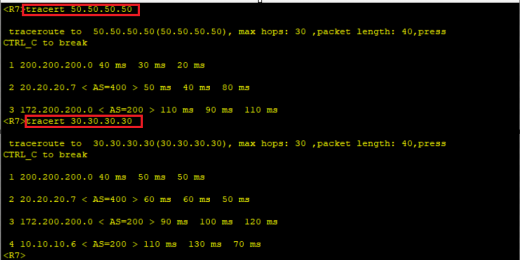
The Loopback 100 on R1, R2, and R7 are used to simulate access networks in the different ASes. When we take a trace from R7 to R 2 the path is as follows: R7>>R5>>R9>>R1>>R2.
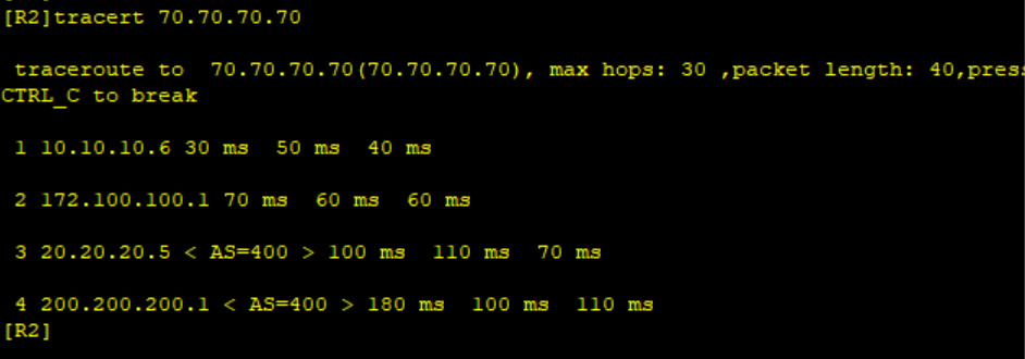
A reverse trace from R2 to R7 follows a similar path as shown.
Let’s now activate the new link between R2 and R6 and confirm traffic flow without changing any BGP attribute to influence traffic flow.
*****************************************R2
interface GigabitEthernet0/0/2
undo shutdown
#
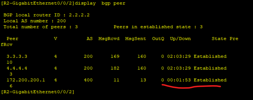
commitConfirm BGP is established between R2 and R6. The peering between R2 and R6 is UP as shown below.
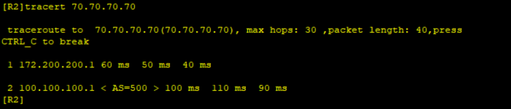
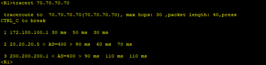
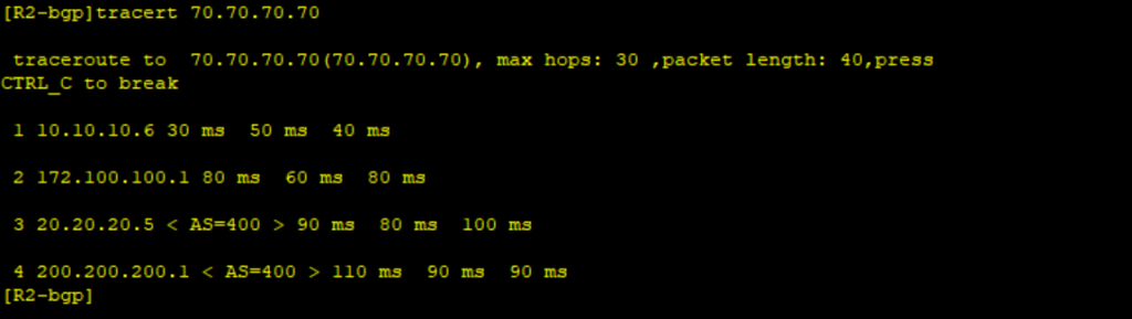
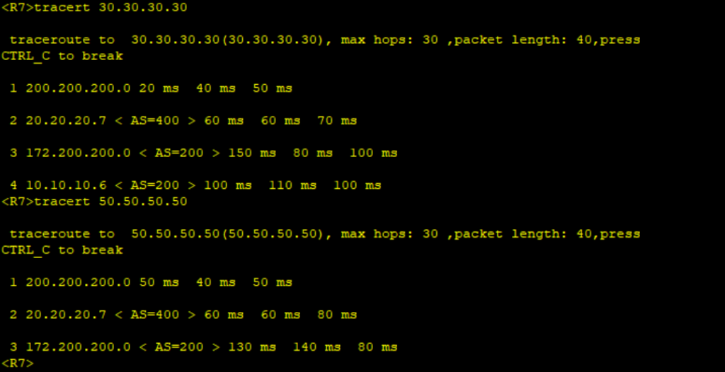
Carry out traces from R2 and R7 to confirm traffic flow. Traffic from R1 and R2 now prefers to use the new integrated low-capacity link instead of the existing link. Similarly, traffic from R7 to R1 and R2 has switched paths to the new integrated link. This is against the objective.
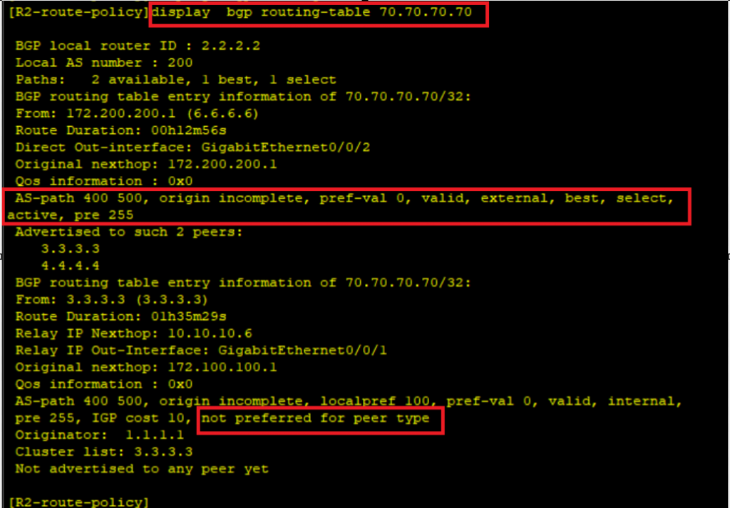
Based on BGP route selection criteria an EBGP route will be preferred over an IBGP route, this is the reason why R2 sends traffic directly to R6. Checking the route of 70.70.70.70 on R2 proves that the route from R6 is preferred because of peer type (EBGP) as shown.
We must force all traffic from AS 200 to exit through the connection between R1 and R9. To achieve this we configure a route policy on R2 to apply lower local preference on routes received from R6 as shown.
*********************************R2
route-policy APPLY_LOWER_LOCAL_PREF permit node 10
 apply local-preference 80
#
bgp 200
 peer 172.200.200.1 route-policy APPLY_LOWER_LOCAL_PREF import
#
commit
Let’s verify the path from R1 and R2 to R7. We also need to verify the reverse path from R7 to R1 and R2.
We have managed to control the outbound traffic of AS 200. We also need to control the inbound traffic of AS 200. All the inbound traffic should be through the connection between R1 and R9 as the primary path. To achieve this by only changing the configuration in AS 200, we create a route policy to prepend AS_PATH to routes advertised to R6 from R2 as shown.
**************************************R2
#
route-policy APPEND_AS_PATH permit node 10
apply as-path 200 200 200 additive
#
bgp 200
peer 172.200.200.1 route-policy APPEND_AS_PATH export
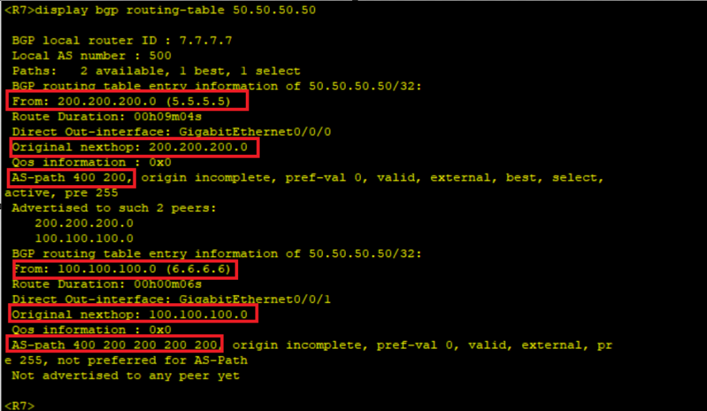
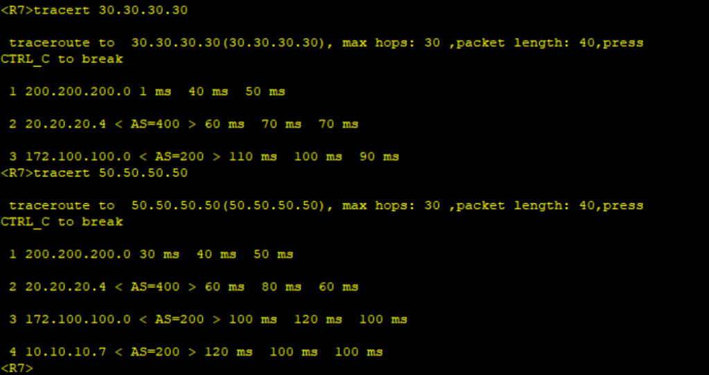
commitVerify the route on R7 and check the forwarding path from R7 to R2 and R1.
1 Comment
Leave a Reply
You must be logged in to post a comment.
[…] Using BGP attributes to control traffic flow among ASes-A real networking case on Huawei Routers […]