
OSPF Advanced Features Simulation on Huawei Routing Devices
- April 21, 2024
- Posted by: Lyfey Technologies
- Categories: Huawei, Networking
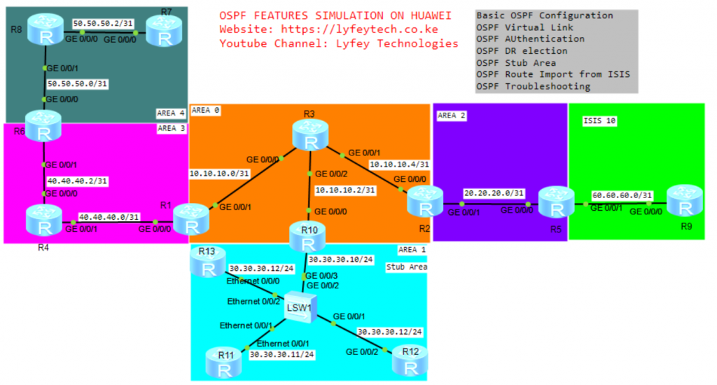
Topology Diagram
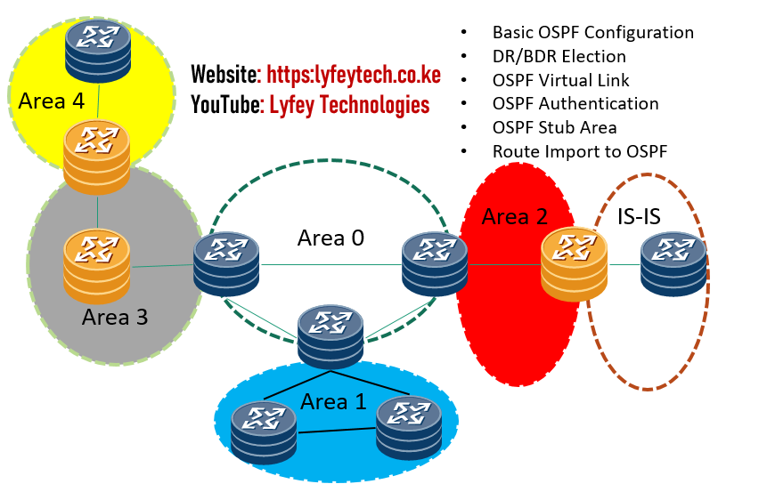
In this lab, we have four OSPF areas: Area 0, Area 1, Area 2, Area 3, and Area 4. The objective is to simulate the following OSPF features:
- Basic OSPF Configuration
- Configure OSPF authentication in Area 0.
- Control DR election in Area 1.
- Configure OSPF virtual link for Area 4 to connect to Area 0.
- Import IS-IS routes to Area 2 and verify external LSAs.
- Configure Area 1 as a stub area.
- General OSPF troubleshooting.
Configuration Steps:
Step 1: Configure the IP address on all the routers in the network.
*************************R1
sys
sysname R1
#
interface Loopback0
ip address 1.1.1.1 32
#
interface GigabitEthernet 0/0/0
ip address 40.40.40.0 31
#
interface GigabitEthernet 0/0/1
ip address 10.10.10.0 31
#
*************************R2
sys
sysname R2
#
interface Loopback0
ip address 2.2.2.2 32
#
interface GigabitEthernet 0/0/0
ip address 10.10.10.5 31
#
interface GigabitEthernet 0/0/1
ip address 20.20.20.0 31
#*************************R3
sys
sysname R3
#
interface Loopback0
ip address 3.3.3.3 32
#
interface GigabitEthernet 0/0/0
ip address 10.10.10.1 31
#
interface GigabitEthernet 0/0/1
ip address 10.10.10.4 31
#
interface GigabitEthernet 0/0/2
ip address 10.10.10.2 31
#*************************R4
sys
sysname R4
#
interface Loopback0
ip address 4.4.4.4 32
#
interface GigabitEthernet 0/0/0
ip address 40.40.40.2 31
#
interface GigabitEthernet 0/0/1
ip address 40.40.40.1 31
#*************************R5
sys
sysname R5
#
interface Loopback0
ip address 5.5.5.5 32
#
interface GigabitEthernet 0/0/0
ip address 20.20.20.1 31
#
interface GigabitEthernet 0/0/1
ip address 60.60.60.0 31
#*************************R6
sys
sysname R6
#
interface Loopback0
ip address 6.6.6.6 32
#
interface GigabitEthernet 0/0/0
ip address 50.50.50.0 31
#
interface GigabitEthernet 0/0/1
ip address 40.40.40.3 31
#*************************R7
sys
sysname R7
#
interface Loopback0
ip address 7.7.7.7 32
#
interface GigabitEthernet 0/0/0
ip address 50.50.50.3 31
#*************************R8
sys
sysname R8
#
interface Loopback0
ip address 8.8.8.8 32
#
interface GigabitEthernet 0/0/0
ip address 50.50.50.2 31
#
interface GigabitEthernet 0/0/1
ip address 50.50.50.1 31
#*************************R9
sys
sysname R9
#
interface Loopback0
ip address 9.9.9.9 32
#
interface GigabitEthernet 0/0/0
ip address 60.60.60.1 31
#*************************R10
sys
sysname R10
#
interface Loopback0
ip address 10.10.10.10 32
#
interface GigabitEthernet 0/0/0
ip address 10.10.10.3 31
#
interface GigabitEthernet 0/0/3
ip address 30.30.30.10 24
#*************************R11
sys
sysname R11
#
interface Loopback0
ip address 11.11.11.11 32
#
interface Ethernet 0/0/1
ip address 30.30.30.11 24
#*************************R12
sys
sysname R12
#
interface Loopback0
ip address 12.12.12.12 32
#
interface GigabitEthernet 0/0/2
ip address 30.30.30.12 24
#*************************R13
sys
sysname R13
#
interface Loopback0
ip address 13.13.13.13 32
#
interface Ethernet 0/0/0
ip address 30.30.30.13 24
#Step 2: Configure OSPF on all routers in Area 0, Area 1, Area 2 Area 3, and Area 4.
****************************R1
ospf 10 router-id 1.1.1.1
 area 0.0.0.0
  network 1.1.1.1 0.0.0.0
  network 10.10.10.0 0.0.0.1
 area 0.0.0.3
  network 40.40.40.0 0.0.0.1
#
****************************R2
ospf 10 router-id 2.2.2.2
area 0.0.0.0
network 2.2.2.2 0.0.0.0
network 10.10.10.4 0.0.0.1
area 0.0.0.2
network 20.20.20.0 0.0.0.1
#****************************R3
ospf 10 router-id 3.3.3.3
area 0.0.0.0
network 3.3.3.3 0.0.0.0
network 10.10.10.4 0.0.0.1
network 10.10.10.2 0.0.0.1
network 10.10.10.0 0.0.0.1
#****************************R4
ospf 10 router-id 4.4.4.4
area 0.0.0.3
network 4.4.4.4 0.0.0.0
network 40.40.40.0 0.0.0.1
network 40.40.40.2 0.0.0.1
#****************************R5
ospf 10 router-id 5.5.5.5
area 0.0.0.2
network 5.5.5.5 0.0.0.0
network 20.20.20.0 0.0.0.1
#****************************R6
ospf 10 router-id 6.6.6.6
area 0.0.0.3
network 6.6.6.6 0.0.0.0
network 40.40.40.2 0.0.0.1
area 0.0.0.4
network 50.50.50.0 0.0.0.1
#****************************R7
ospf 10 router-id 7.7.7.7
area 0.0.0.4
network 7.7.7.7 0.0.0.0
network 50.50.50.2 0.0.0.1
#****************************R8
ospf 10 router-id 8.8.8.8
area 0.0.0.4
network 8.8.8.8 0.0.0.0
network 50.50.50.0 0.0.0.1
network 50.50.50.2 0.0.0.1
#****************************R10
ospf 10 router-id 10.10.10.10
area 0.0.0.0
network 10.10.10.10 0.0.0.0
network 10.10.10.2 0.0.0.1
area 0.0.0.1
network 30.30.30.0 0.0.0.255
#****************************R11
ospf 10 router-id 11.11.11.11
area 0.0.0.1
network 30.30.30.0 0.0.0.255
#****************************R12
ospf 10 router-id 12.12.12.12
area 0.0.0.1
network 30.30.30.0 0.0.0.255
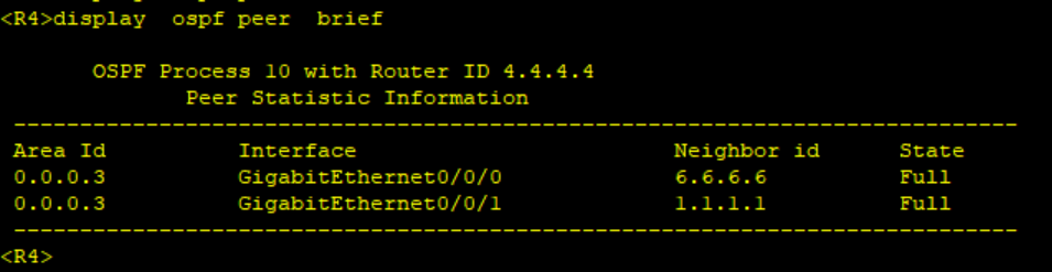
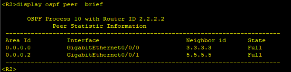
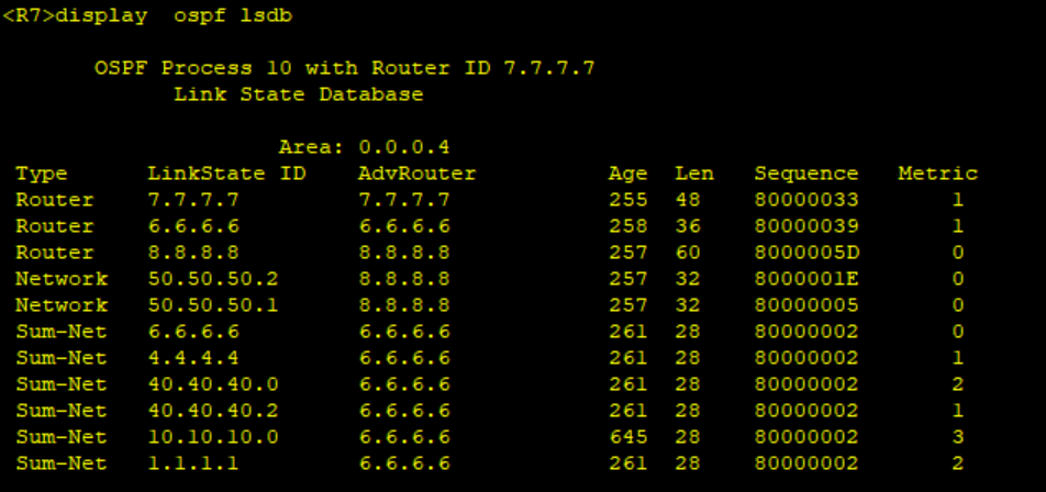
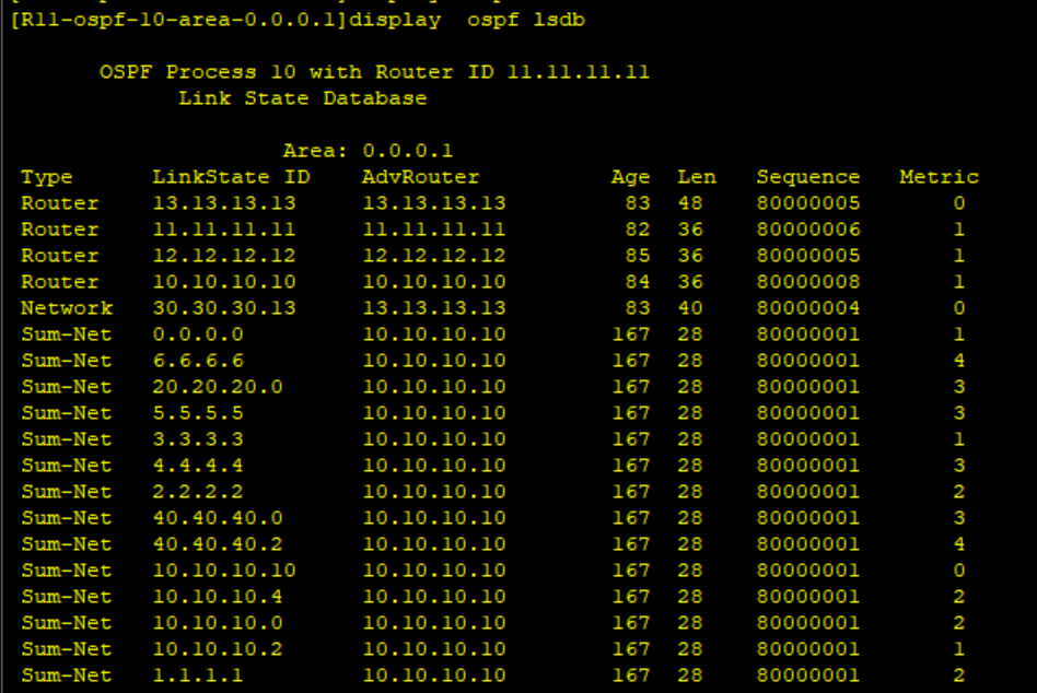
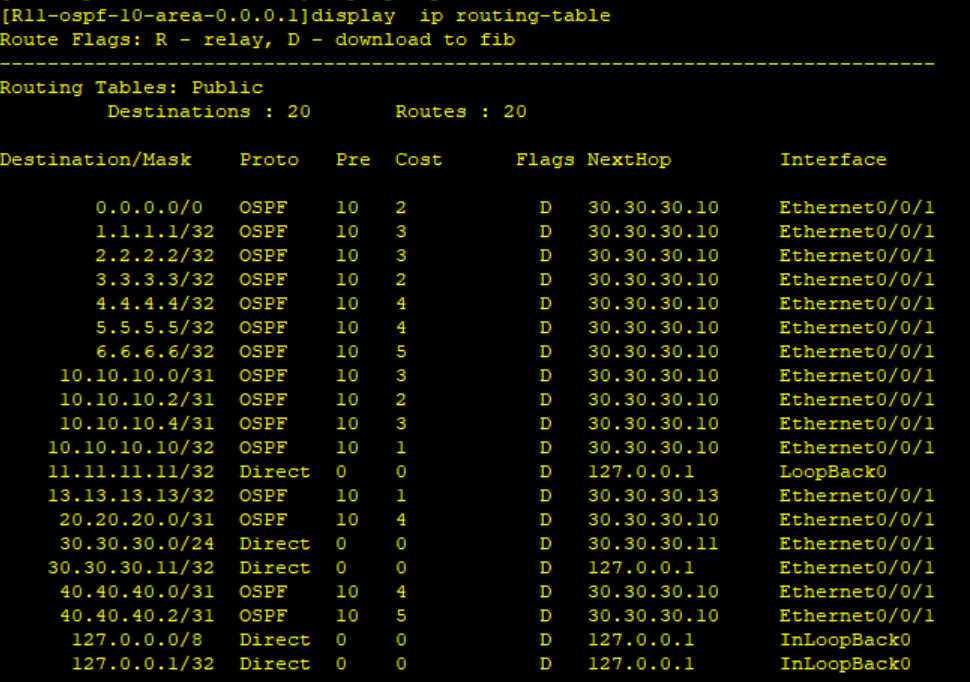
#Step 3: Verify OSPF status on the routers. Check OSPF LSDBs and routing table on different routers.
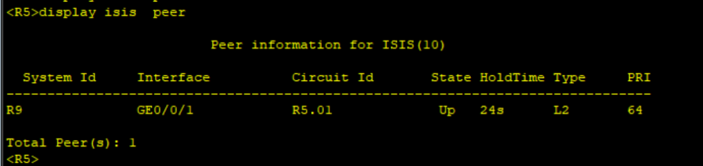
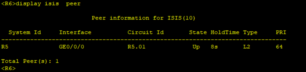
Step 4: Configure ISIS on R5 and R9.
*********************R5
isis 10
 is-level level-2
 cost-style wide
 network-entity 49.0010.0000.0000.0005.00
 is-name R5
#
interface GigabitEthernet0/0/1
 ip address 60.60.60.0 255.255.255.254
 isis enable 10
**********************R9
isis 10
is-level level-2
cost-style wide
network-entity 49.0010.0000.0000.0009.00
is-name R9
#
interface GigabitEthernet0/0/0
isis enable 10Step 5: Verify ISIS status on R5 and R9.
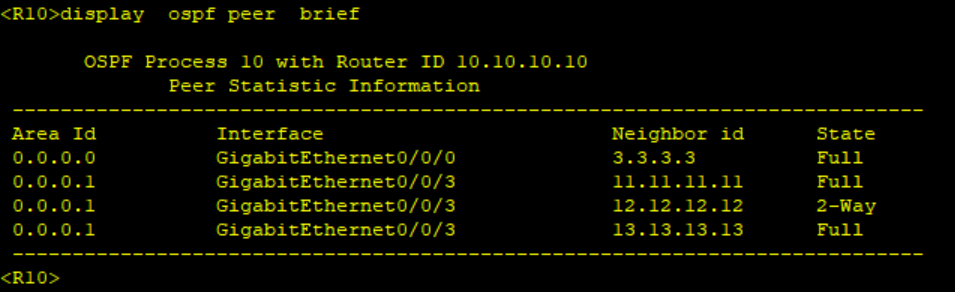
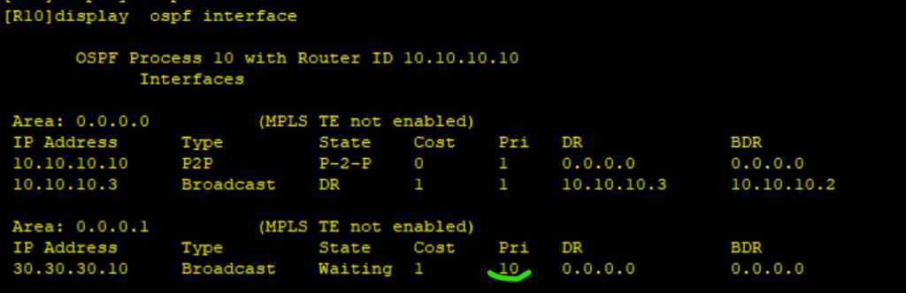
On Broadcast network, the DR/BDR is elected to reduce the number of OSPF adjacencies in the network. Routers only establish adjacencies with the DR and the BDR. DROther routers do not establish adjacency among themselves. On Huawei devices, the router with the highest DR-priority is elected as the DR. The default DR-priority is 1 hence we need the second criteria to select the DR and BDR. When the DR-priority is same on all routers, the router with the highest router ID is selected as the DR. You can manually configure the DR priority to control which router becomes the DR in the network.
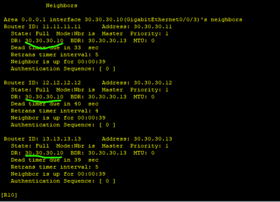
Step 6: Configure DR priority on R10 to force it to be elected at the DR.
********************************R10
#
interface GigabitEthernet0/0/3
 ospf dr-priority 10
#
Shut down all ports on the switch to force adjacency to refresh on all routers in Area 1. Verify R10 is now the DR.
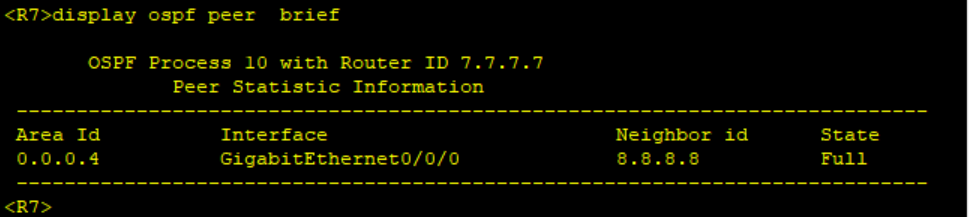
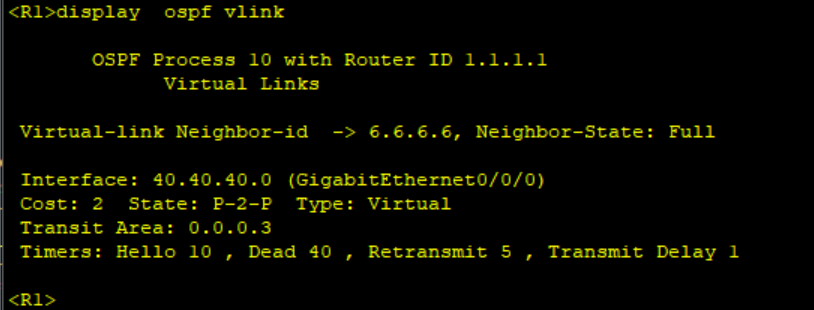
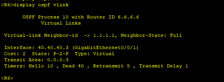
Step 7: Configure OSPF Virtual link for Area 4 on R6 and R1.
When designing OSPF areas, its a requiremenet that all non backbone areas should have a connection to Backbone area (Area 0). Sometimes this is impossible and you need to create a virtual link for the remote non backbone network so as to connect it to the backbone.
****************************R1
ospf 10
 area 0.0.0.3
 vlink-peer 6.6.6.6
#
****************************R6
ospf 10
area 0.0.0.3
vlink-peer 1.1.1.1
#Verify the status of the Virtual link and confirm that Routers Area 0 are receiving LSAs and routes from Area 4 and vice versa.
Step 8: Configure Authentication in Area 0 on routers R1, R2, R3 and R10.
We configure MD5 area authentication. You can also configure authentication on the interface. Interface authentication takes precedence over area authentication. Note: The authentication mode and the Password should be the same on both routers for adjacency to come up.
******************************r1, R2, R3 R10
ospf 10
 area 0.0.0.0
 authentication-mode md5 1 cipher Huawei@123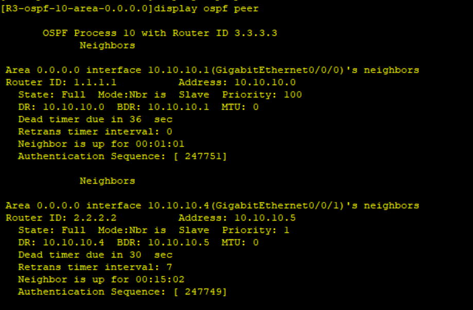
Step 9: Import IS-IS to OSPF and check the presence of external LSAs in Area 1.
*************************R5
ospf 10
 import-route isis 10
Step 10: Configure Area 1 as Stub Area.
The stub command should be configured on all routers in the stub area for it to take effect.
**************************R10,R11,R12,R13
ospf 10
 area 0.0.0.1
 stub
#
Verify that we don’t have external LSAs on routers in Area 1 and there is a default route injected.
Thank you for reading our article and please remember to check our YouTube channel with step by step explanation of this lab: Lyfey Technologies Youtube Channel
Latest Posts
- Step by step guide on how to implement different networking protocols on Juniper MX routers
- L2 EVPN Implementation on Huawei Routers.
- VRRP Monitoring of the Uplink Interface status on Huawei routers.
- Association between VRRP and BFD Implementation on Huawei routers.
- Association between VRRP and STP Implementation on Huawei routers.
Leave a Reply
You must be logged in to post a comment.