
Introduction to VPLS and Lab Simulation on Huawei Routers
- January 19, 2024
- Posted by: Lyfey Technologies
- Category: Huawei
What is a VPLS(Virtual Private LAN Service)
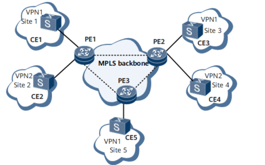
A VPLS is an MPLS-based Ethernet point-to-multipoint (P2MP) L2VPN service provided over a public network. VPLS ensures that geographically isolated customer sites can communicate over MANs or WANs as if they were on the same LAN. VPLS uses either LDP or BGP as the signaling protocol.
From the perspective of the customer, the MPLS IP backbone network is a layer 2 switching device. The PE routers don’t need to learn and keep customer routing information.
Benefits of VPLS
Below are the main benefits of VPLS:
- VPLS networks can be constructed based on the carrier’s IP backbone networks, reducing construction costs.
- VPLS networks allow users to communicate over Ethernet links, regardless of whether these links are on WANs or LANs. This feature allows services to be rapidly and flexibly deployed.
- VPLS networks free carriers from configuring and maintaining routing policies, reducing operational expenditure.
VPLS Lab Topology Setup
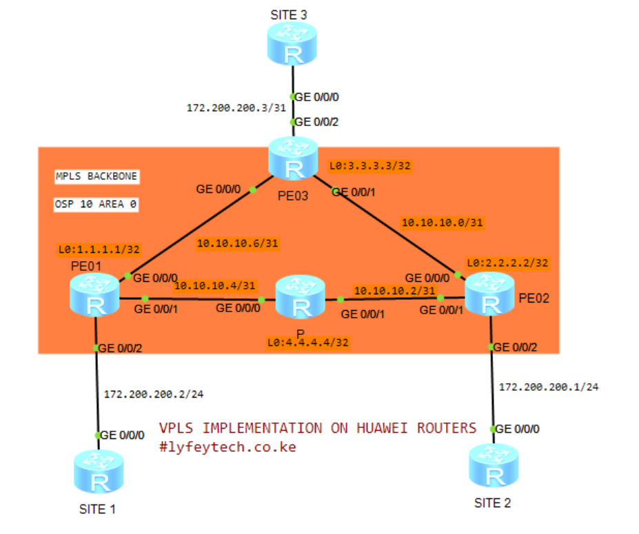
Below is our lab setup. The objective is to configure VPLS on the MPLS backbone network and ensure communication between the three customer sites. LDP is used as the signaling protocol.
Configuration steps
The configuration steps are as follows:
Step 1: Configure MPLS LSR-ID, and enable MPLS, MPLS LDP, and MPLS L2VPN globally on PE01, PE02, PE03, and P routers. Configure IP address on interfaces in the IP backbone network. Enable MPLS and MPLS LDP on the interfaces in the MPLS Backbone.
************************PE01
sysname PE01
#
mpls lsr-id 1.1.1.1
mpls
#
mpls l2vpn
#
interface Loopback 0
ip address 3.3.3.3 32
#
interface GigabitEthernet0/0/0
ip address 10.10.10.7 31
mpls
mpls ldp
#
interface GigabitEthernet0/0/1
ip address 10.10.10.1 31
mpls
mpls ldp
#
commit
*************************************PE02
#
sysname PE02
#
mpls lsr-id 2.2.2.2
mpls
#
mpls l2vpn
#
interface LoopBack0
ip address 2.2.2.2 255.255.255.255
#
interface GigabitEthernet0/0/0
ip address 10.10.10.0 255.255.255.254
mpls
mpls ldp
#
interface GigabitEthernet0/0/1
ip address 10.10.10.2 255.255.255.254
mpls
mpls ldp
#
commit****************************PE03
sys
#
sysname PE03
#
mpls lsr-id 3.3.3.3
mpls
#
mpls l2vpn
#
interface GigabitEthernet0/0/0
ip address 10.10.10.7 255.255.255.254
mpls
mpls ldp
#
interface GigabitEthernet0/0/1
ip address 10.10.10.1 255.255.255.254
mpls
mpls ldp
#
interface LoopBack0
ip address 3.3.3.3 255.255.255.255
#
commit*****************************P01
#
sysname P01
#
mpls lsr-id 4.4.4.4
mpls
#
mpls l2vpn
#
mpls ldp
#
interface GigabitEthernet0/0/0
ip address 10.10.10.5 255.255.255.254
mpls
mpls ldp
#
interface GigabitEthernet0/0/1
ip address 10.10.10.3 255.255.255.254
mpls
mpls ldp
#
interface LoopBack0
ip address 4.4.4.4 255.255.255.255
#
commitStep 2: Configure OSPF routing protocol on routers in the backbone network to achieve connectivity between devices.
**********************************PE01
#
ospf 10 router-id 1.1.1.1
 area 0.0.0.0
  network 1.1.1.1 0.0.0.0
  network 10.10.10.6 0.0.0.1
  network 10.10.10.4 0.0.0.1
#
*********************************PE02
#
ospf 10 router-id 2.2.2.2
area 0.0.0.0
network 2.2.2.2 0.0.0.0
network 10.10.10.0 0.0.0.1
network 10.10.10.2 0.0.0.1
#*********************************PE03
#
ospf 10 router-id 3.3.3.3
area 0.0.0.0
network 3.3.3.3 0.0.0.0
network 10.10.10.6 0.0.0.1
network 10.10.10.0 0.0.0.1
#********************************P01
ospf 10 router-id 4.4.4.4
area 0.0.0.0
network 4.4.4.4 0.0.0.0
network 10.10.10.4 0.0.0.1
network 10.10.10.2 0.0.0.1
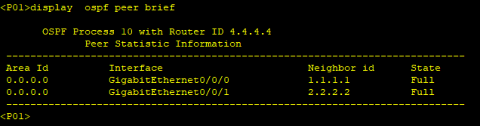
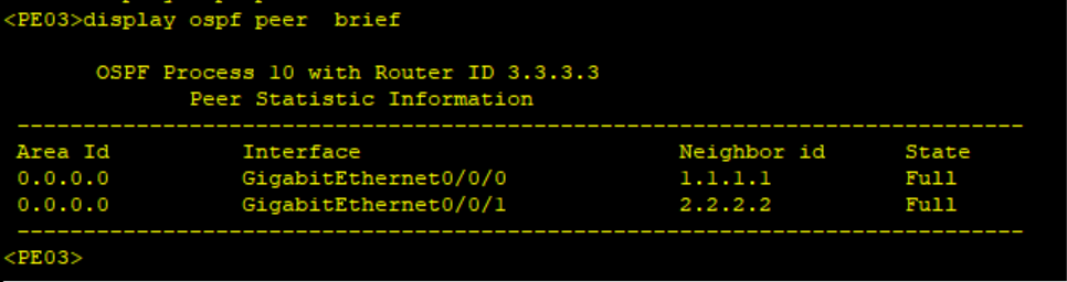
#Confirm the OSPF status and connectivity among PEs and P routers.
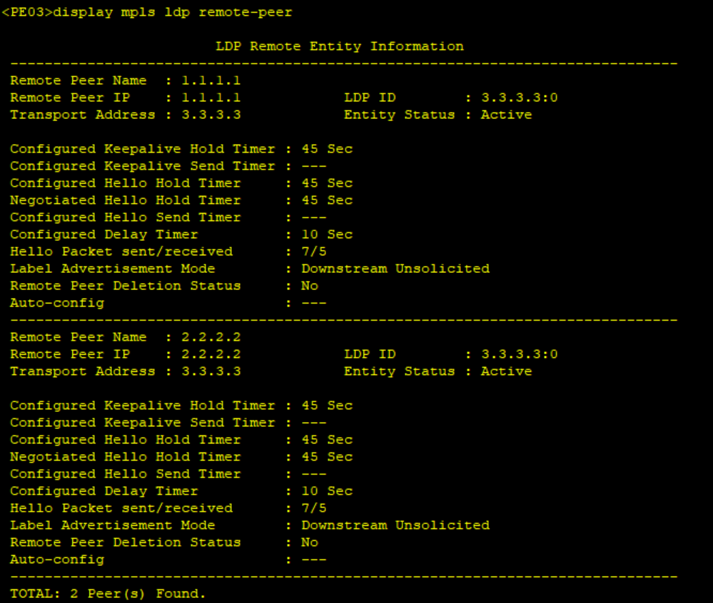
Step 3: Configure remote LDP sessions between PEs.
****************************PE01

mpls ldp remote-peer 2.2.2.2
 remote-ip 2.2.2.2
#
mpls ldp remote-peer 3.3.3.3
 remote-ip 3.3.3.3
#
Verify MPLS LDP session status
Step 4: Create VSIs on PEs, set the signaling protocol to LDP, and bind VSIs to AC interfaces connecting the customer sites.
*******************************PE01
vsi 333
 pwsignal ldp
  vsi-id 333
  peer 3.3.3.3
  peer 2.2.2.2
#
interface GigabitEthernet0/0/2.333
 vlan-type dot1q 333
 l2 binding vsi 333
#
******************************PE02
vsi 333
pwsignal ldp
vsi-id 333
peer 3.3.3.3
peer 1.1.1.1
#
interface GigabitEthernet0/0/2.333
vlan-type dot1q 333
l2 binding vsi 333
#******************************PE03
vsi 333
pwsignal ldp
vsi-id 333
peer 1.1.1.1
peer 2.2.2.2
#
interface GigabitEthernet0/0/2.333
vlan-type dot1q 333
l2 binding vsi 333
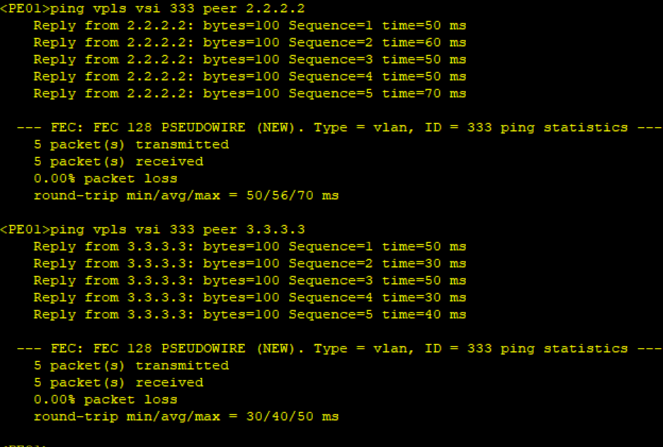
#Verify VPLS status on PEs. We can ping the VPLS from PE01 to PE02 and PE03 as shown below. This confirms that our VPLS is working OK.
Step 5: Configure service Interfaces on customer sites.
*************************SITE01
sys
sysname SITE01
#
interface Gig 0/0/0.333
vlan-type dot1q 333
ip address 172.200.200.2 24
#
**************************SITE02
sys
sysname SITE02
#
interface Gig 0/0/0.333
vlan-type dot1q 333
ip address 172.200.200.1 24***************************SITE03
sys
sysname SITE03
#
interface Gig 0/0/0.333
vlan-type dot1q 333
ip address 172.200.200.1 24
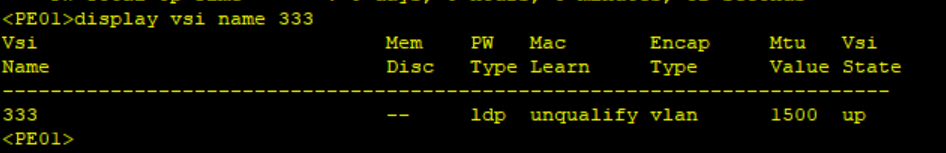
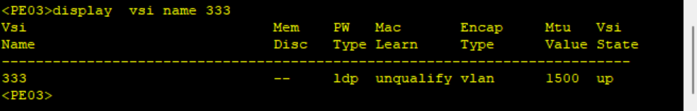
#Step 6: Verify VPLS status and confirm communication between sites.
Run the command display vsi name 333 verbose to confirm the status of VPLS
Ping Site 2 and Site 3 from Site 1 to confirm communication among the three sites
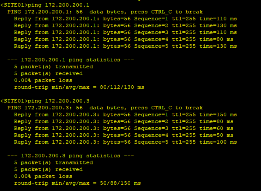
We can ping Site 2 and Site 3 from Site 1. The customer traffic is transparent on the Service provider network hence we are not able to capture the ping packets on the backbone network.
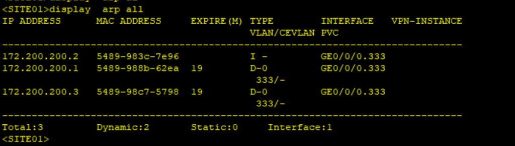
The backbone network acts like a switch for the customer, the sites forward traffic based on MAC addresses as shown below.
392 Comments
Leave a Reply
You must be logged in to post a comment.
This is awesome. Thanks for sharing.
Thank you so much the more informative lectures and labs,much appreciated