
Intra-AS Seamless MPLS implementation On Huawei Routers
- April 6, 2024
- Posted by: Lyfey Technologies
- Categories: Huawei, Networking
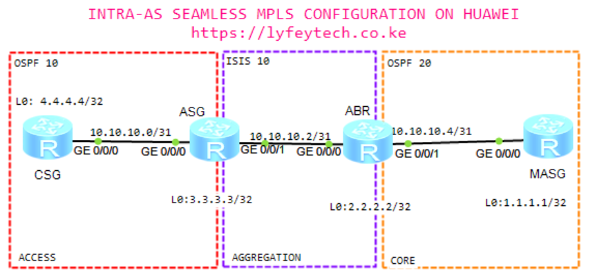
Step 1: Configure hostname and IP addresses on all the routers.
*********************************CSG
sys
#
sysname CSG
#
interface GigabitEthernet0/0/0
 ip address 10.10.10.1 255.255.255.254
#
interface LoopBack0
 ip address 4.4.4.4 255.255.255.255
#
*********************************ASG
sys
#
sysname ASG
#
interface GigabitEthernet0/0/0
ip address 10.10.10.0 255.255.255.254
#
interface GigabitEthernet0/0/1
ip address 10.10.10.3 255.255.255.254
#
interface LoopBack0
ip address 3.3.3.3 255.255.255.255
#*********************************ABR
sys
#
sysname ABR
#
interface GigabitEthernet0/0/0
ip address 10.10.10.2 255.255.255.254
#
interface GigabitEthernet0/0/1
ip address 10.10.10.5 255.255.255.254
#
interface LoopBack0
ip address 2.2.2.2 255.255.255.255
#*********************************MASG
sys
#
sysname MASG
#
interface GigabitEthernet0/0/0
ip address 10.10.10.4 255.255.255.254
interface LoopBack0
ip address 1.1.1.1 255.255.255.255
#Step 2: Configure MPLS and MPLS LDP on all the routers. Enable MPLS and MPLS LDP on interfaces
****************************CSG
#
mpls lsr-id 4.4.4.4
mpls
#
mpls ldp
#
interface GigabitEthernet0/0/0
mpls
mpls ldp
****************************ASG
#
mpls lsr-id 3.3.3.3
mpls
#
mpls ldp
#
interface GigabitEthernet0/0/0
mpls
mpls ldp
#
interface GigabitEthernet0/0/1
mpls
mpls ldp****************************ABR
#
mpls lsr-id 2.2.2.2
mpls
#
mpls ldp
#
interface GigabitEthernet0/0/0
mpls
mpls ldp
#
interface GigabitEthernet0/0/1
mpls
mpls ldp****************************MASG
#
mpls lsr-id 1.1.1.1
mpls
#
mpls ldp
#
interface GigabitEthernet0/0/0
mpls
mpls ldpStep 3: Configure IGP in access, aggregation, and core layers.
*****************************CSG
#
ospf 10 router-id 4.4.4.4
 area 0.0.0.0
  network 4.4.4.4 0.0.0.0
  network 10.10.10.0 0.0.0.1
#
*****************************ASG
#
ospf 10 router-id 3.3.3.3
area 0.0.0.0
network 3.3.3.3 0.0.0.0
network 10.10.10.0 0.0.0.1
#
isis 10
is-level level-2
cost-style wide
network-entity 49.0010.0030.0300.3003.00
is-name ASG
#
interface GigabitEthernet0/0/1
isis enable 10
#
interface Loopback0
isis enable 10*****************************ABR
#
ospf 20 router-id 2.2.2.2
area 0.0.0.0
network 2.2.2.2 0.0.0.0
network 10.10.10.4 0.0.0.1
#
isis 10
is-level level-2
cost-style wide
network-entity 49.0010.0020.0200.2002.00
is-name ABR
#
interface GigabitEthernet0/0/0
isis enable 10
#
interface Loopback0
isis enable 10*****************************MASG
#
ospf 20 router-id 1.1.1.1
area 0.0.0.0
network 1.1.1.1 0.0.0.0
network 10.10.10.4 0.0.0.1
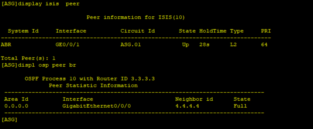
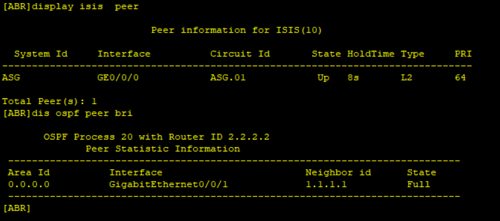
#Verify IGP running status on all the routers.
Step 4: Configure BGP peering at each layer and enable devices to exchange labeled routes.
*********************************CSG
#
bgp 500
 router-id 4.4.4.4
 peer 3.3.3.3 as-number 500
 peer 3.3.3.3 connect-interface LoopBack0
 #
 ipv4-family unicast
  network 4.4.4.4 255.255.255.255
  peer 3.3.3.3 enable
  peer 3.3.3.3 label-route-capability
#
*********************************ASG
#
bgp 500
router-id 3.3.3.3
peer 4.4.4.4 as-number 500
peer 4.4.4.4 connect-interface LoopBack0
peer 2.2.2.2 as-number 500
peer 2.2.2.2 connect-interface LoopBack0
#
ipv4-family unicast
peer 4.4.4.4 enable
peer 4.4.4.4 label-route-capability
peer 2.2.2.2 enable
peer 2.2.2.2 label-route-capability
#*********************************ABR
#
bgp 500
router-id 2.2.2.2
peer 1.1.1.1 as-number 500
peer 1.1.1.1 connect-interface LoopBack0
peer 3.3.3.3 as-number 500
peer 3.3.3.3 connect-interface LoopBack0
#
ipv4-family unicast
peer 1.1.1.1 enable
peer 1.1.1.1 label-route-capability
peer 3.3.3.3 enable
peer 3.3.3.3 label-route-capability
#*********************************MASG
#
bgp 500
router-id 1.1.1.1
peer 2.2.2.2 as-number 500
peer 2.2.2.2 connect-interface LoopBack0
#
ipv4-family unicast
network 2.2.2.2 255.255.255.255
peer 2.2.2.2 enable
peer 2.2.2.2 label-route-capability
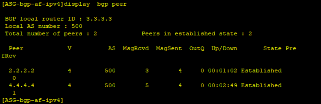
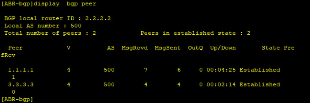
#Verify BGP peering status on all routers.
Step 5: Configure ASG and ABR as the RRs to advertise routes from CSG to MASG and vice-versa
**************************ASG
bgp 500
peer 4.4.4.4 reflect-client
peer 4.4.4.4 next-hop-local
peer 2.2.2.2 reflect-client
peer 2.2.2.2 next-hop-local
**************************ABR
bgp 500
peer 1.1.1.1 reflect-client
peer 1.1.1.1 next-hop-local
peer 3.3.3.3 reflect-client
peer 3.3.3.3 next-hop-localStep 6: Configure a routing policy on each device to establish a BGP LSP
*************************CSG
#
route-policy ADVERTISE_ROUTES permit node 10
 apply mpls-label
#
bgp 500
  peer 3.3.3.3 route-policy ADVERTISE_ROUTES export
#
************************ASG
#
route-policy ADVERTISE_ROUTES permit node 10
if-match mpls-label
apply mpls-label
#
bgp 500
peer 2.2.2.2 route-policy ADVERTISE_ROUTES export
peer 4.4.4.4 route-policy ADVERTISE_ROUTES export
#************************ABR
#
route-policy ADVERTISE_ROUTES permit node 10
if-match mpls-label
apply mpls-label
#
bgp 500
peer 3.3.3.3 route-policy ADVERTISE_ROUTES export
peer 1.1.1.1 route-policy ADVERTISE_ROUTES export
#*************************MASG
#
route-policy ADVERTISE_ROUTES permit node 10
apply mpls-label
#
bgp 500
peer 2.2.2.2 route-policy ADVERTISE_ROUTES export
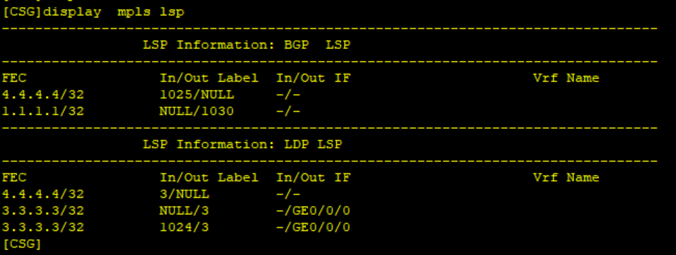
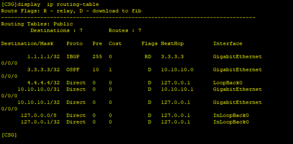
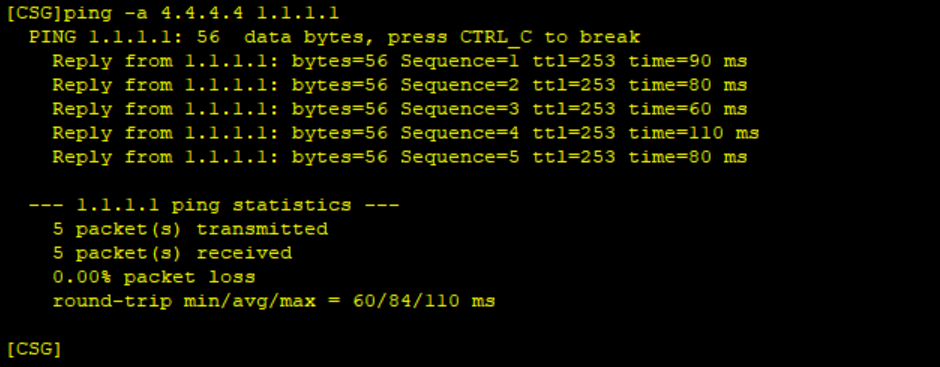
#Verify the connectivity between CSG and MASG.
Thank You for reading and please remember your comments and share our article.
Related Posts
- Step by step guide on how to implement different networking protocols on Juniper MX routers
- L2 EVPN Implementation on Huawei Routers.
- VRRP Monitoring of the Uplink Interface status on Huawei routers.
- Association between VRRP and BFD Implementation on Huawei routers.
- Association between VRRP and STP Implementation on Huawei routers.
387 Comments
Leave a Reply
You must be logged in to post a comment.
Thank you so much for sharing, your contribution in growing my knowledge base is highly appreciated