
Implementing Virtual Private Wire Service (VPWS) on Nokia Routers
- March 31, 2024
- Posted by: Lyfey Technologies
- Categories: Networking, Nokia
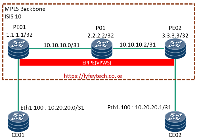
Step 1: Configure ports on all the routers. On CE01 and CE02 we configure the ports to PEs mode to hybrid. On PE01 and PE02 we configure ports facing the CEs as access ports.
******************************CE01
configure
    port 1/x1/1/c1/1
        description "to R1 1/x1/1/c3/1"
        ethernet
            mode hybrid
            encap-type dot1q
            lldp
                dest-mac nearest-bridge
                    admin-status tx-rx
                    notification
                    tx-tlvs port-desc sys-cap
                    tx-mgmt-address system
                exit
            exit
        exit
        no shutdown
    exit
******************************PE01
configure
port 1/x1/1/c1/1
description "to R1 1/x1/1/c3/1"
ethernet
mode access
encap-type dot1q
lldp
dest-mac nearest-bridge
admin-status tx-rx
notification
tx-tlvs port-desc sys-cap
tx-mgmt-address system
exit
exit
exit
no shutdown
exit
port 1/x1/1/c2/1
ethernet
lldp
dest-mac nearest-bridge
admin-status tx-rx
notification
tx-tlvs port-desc sys-cap
tx-mgmt-address system
exit
exit
exit
no shutdown
exit******************************P01
configure
port 1/x1/1/c1/1
description "to R1 1/x1/1/c3/1"
ethernet
lldp
dest-mac nearest-bridge
admin-status tx-rx
notification
tx-tlvs port-desc sys-cap
tx-mgmt-address system
exit
exit
exit
no shutdown
exit
port 1/x1/1/c2/1
ethernet
lldp
dest-mac nearest-bridge
admin-status tx-rx
notification
tx-tlvs port-desc sys-cap
tx-mgmt-address system
exit
exit
exit
no shutdown
exit******************************PE02
configure
port 1/x1/1/c1/1
description "to R1 1/x1/1/c3/1"
ethernet
lldp
dest-mac nearest-bridge
admin-status tx-rx
notification
tx-tlvs port-desc sys-cap
tx-mgmt-address system
exit
exit
exit
no shutdown
exit
port 1/x1/1/c2/1
ethernet
mode access
encap-type dot1q
mtu 8000
lldp
dest-mac nearest-bridge
admin-status tx-rx
notification
tx-tlvs port-desc sys-cap
tx-mgmt-address system
exit
exit
exit
no shutdown
exit*****************************CE02
configure
port 1/x1/1/c1/1
description "to R1 1/x1/1/c3/1"
ethernet
mode hybrid
encap-type dot1q
lldp
dest-mac nearest-bridge
admin-status tx-rx
notification
tx-tlvs port-desc sys-cap
tx-mgmt-address system
exit
exit
exit
no shutdown
exitStep 2 : Configure interfaces in MPLS backbone.
****************************PE01
configure router
        interface "TO_R3"
            address 10.10.10.0/31
            port 1/x1/1/c2/1
            no shutdown
        exit
        interface "system"
            address 2.2.2.2/32
            no shutdown
        exit
*****************************P01
/configure router
interface "TO_R2"
address 10.10.10.1/31
port 1/x1/1/c1/1
no shutdown
exit
interface "TO_R4"
address 10.10.10.2/31
port 1/x1/1/c2/1
no shutdown
exit
interface "system"
address 3.3.3.3/32
no shutdown
exit*****************************PE02
/configure router
interface "TO_R3"
address 10.10.10.3/31
port 1/x1/1/c1/1
no shutdown
exit
interface "system"
address 4.4.4.4/32
no shutdown
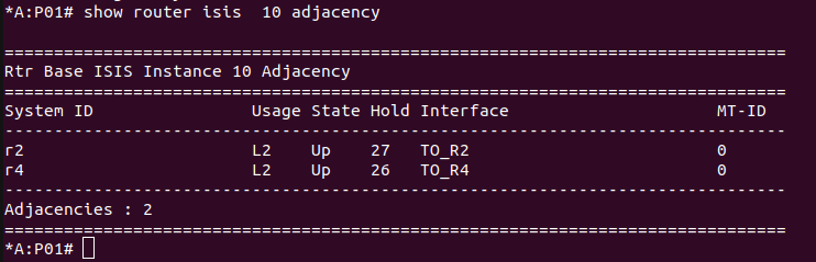
exitStep 3: Configure IS-IS in the MPLS backbone and verify adjaceny status.
***************************PE01
/configure router
        isis 10
            level-capability level-2
            interface "system"
                level-capability level-2
                no shutdown
            exit
            interface "TO_R3"
                level-capability level-2
                no shutdown
            exit
            no shutdown
        exit
*******************************P01
/configure router
isis 10
level-capability level-2
interface "system"
level-capability level-2
no shutdown
exit
interface "TO_R2"
level-capability level-2
no shutdown
exit
interface "TO_R4"
level-capability level-2
no shutdown
exit
no shutdown
exit******************************PE02
/configure router
isis 10
level-capability level-2
interface "system"
level-capability level-2
no shutdown
exit
interface "TO_R3"
level-capability level-2
no shutdown
exit
no shutdown
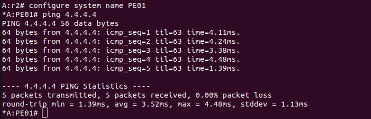
exitVerify IS-IS status on P01 and confirm you can ping PE02 from PE01
Step 4: Configure MPLS and LDP on all routers in the MPLS backbone.
***************************PE01
configure router
        mpls
            interface "system"
                no shutdown
            exit
            interface "TO_R3"
                no shutdown
            exit
        no shutdown
        exit
        ldp
            import-pmsi-routes
            exit
            tcp-session-parameters
                peer-transport 4.4.4.4
                exit
            exit
            interface-parameters
                interface "TO_R3" dual-stack
                    ipv4
                        no shutdown
                    exit
                    no shutdown
                exit
            exit
            targeted-session
            exit
******************************P01
configure router
mpls
interface "system"
no shutdown
exit
interface "TO_R2"
no shutdown
exit
interface "TO_R4"
no shutdown
exit
no shutdown
exit
ldp
import-pmsi-routes
exit
tcp-session-parameters
exit
interface-parameters
interface "TO_R2" dual-stack
ipv4
no shutdown
exit
no shutdown
exit
interface "TO_R4" dual-stack
ipv4
no shutdown
exit
no shutdown
exit
exit
targeted-session
exit
no shutdown
exit
exit********************************PE02
configure router
mpls
interface "system"
no shutdown
exit
interface "TO_R3"
no shutdown
exit
no shutdown
exit
ldp
import-pmsi-routes
exit
tcp-session-parameters
peer-transport 2.2.2.2
exit
exit
interface-parameters
interface "TO_R3" dual-stack
ipv4
no shutdown
exit
no shutdown
exit
exit
targeted-session
exit
no shutdown
exit
exitStep 5: Configure SDP (Service Distribution Point) on PE01 and PE02, verify SDP status on both PEs.
**************************PE01
/configure service
       sdp 10004 mpls create
            far-end 4.4.4.4
            ldp
            keep-alive
                shutdown
            exit
            no shutdown
        exit
************************PE02
/configure service
sdp 1002 mpls create
far-end 2.2.2.2
ldp
keep-alive
shutdown
exit
no shutdown
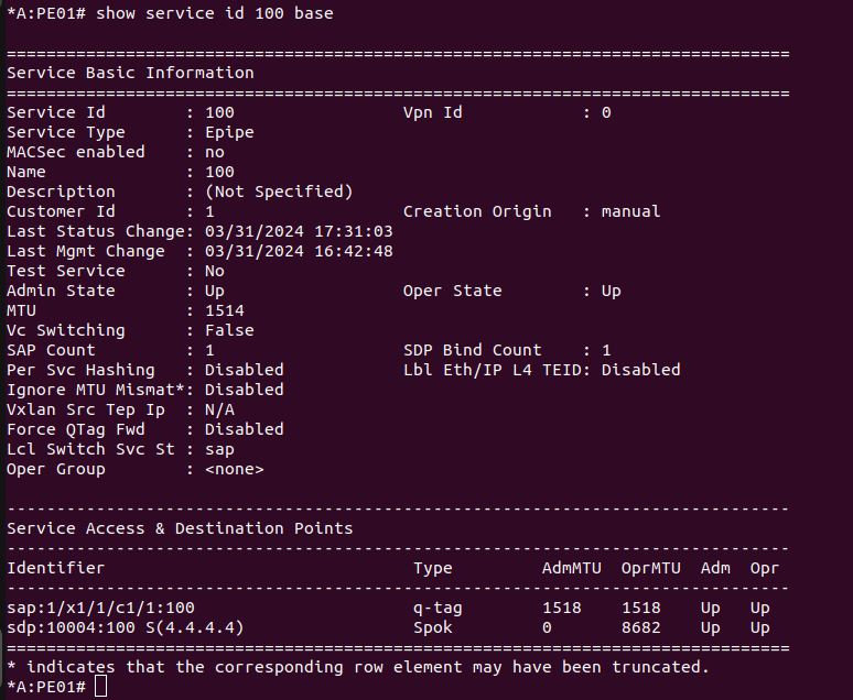
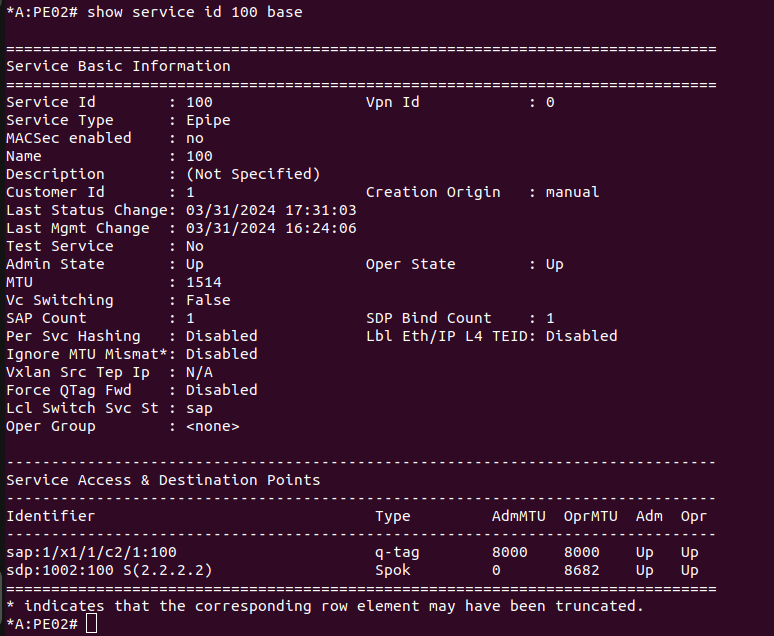
exitStep 6: Configure Epipe(VPWS) on PE01 and PE02 and verify status on both PEs.
****************************PE01
configure service
        epipe 100 name "100" customer 1 create
            sap 1/x1/1/c1/1:100 create
                no shutdown
            exit
            spoke-sdp 10004:100 create
                no shutdown
            exit
            no shutdown
        exit
****************************PE02
configure service
epipe 100 name "100" customer 1 create
sap 1/x1/1/c2/1:100 create
no shutdown
exit
spoke-sdp 1002:100 create
no shutdown
exit
no shutdown
exitVerify EPIPE status
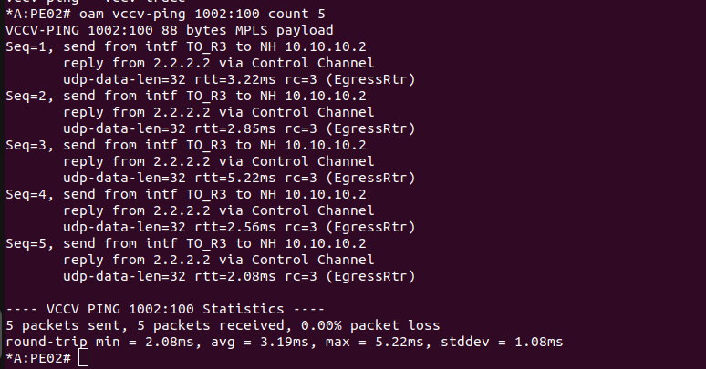
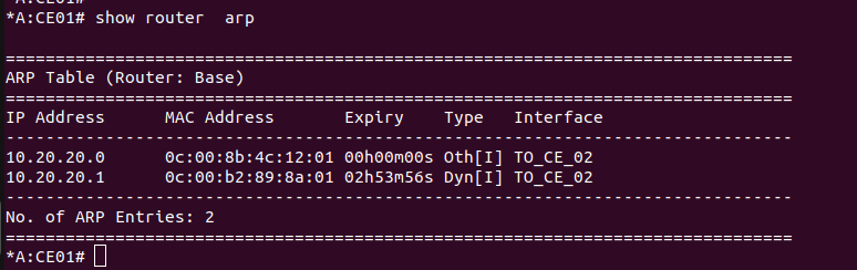
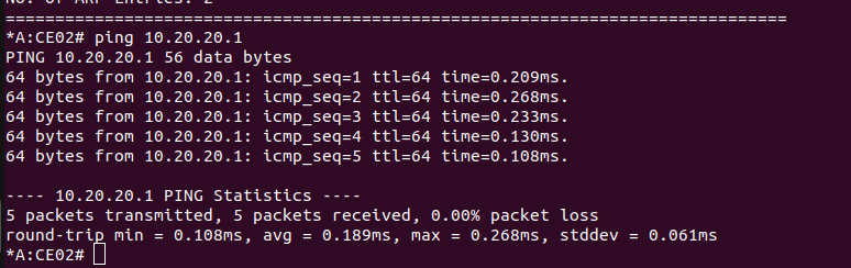
Step 7: Configure L3 interfaces on CE01 and CE02 using VLAN 100 and verify connecting between the CEs.
******************************CE01
interface "TO_CE_02"
address 10.20.20.0/31
port 1/x1/1/c1/1:100
no shutdown
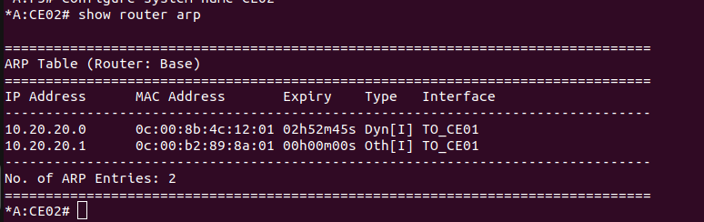
exit******************************CE02
interface "TO_CE_01"
address 10.20.20.1/31
port 1/x1/1/c1/1:100
no shutdown
exitVerify connectivity between CE01 and CE02
Thank you for reading our content. Please leave your comments below and check our blog for more related posts.
Related Posts
- Step by step guide on how to implement different networking protocols on Juniper MX routers
- L2 EVPN Implementation on Huawei Routers.
- VRRP Monitoring of the Uplink Interface status on Huawei routers.
- Association between VRRP and BFD Implementation on Huawei routers.
- Association between VRRP and STP Implementation on Huawei routers.
Leave a Reply
You must be logged in to post a comment.