
Implementing PWE3(L2VPN) on Nodes in different IGP Domains on Huawei Routers
- April 17, 2024
- Posted by: Lyfey Technologies
- Categories: Huawei, Networking
In our last article, we demonstrated how to configure an L2VPN on routers within the same IGP domain: Implementation of PWE3 on Huawei Routers. Today’s article demonstrates how to configure a Pseudowire on routers in different IGP domains.
Configuration Steps
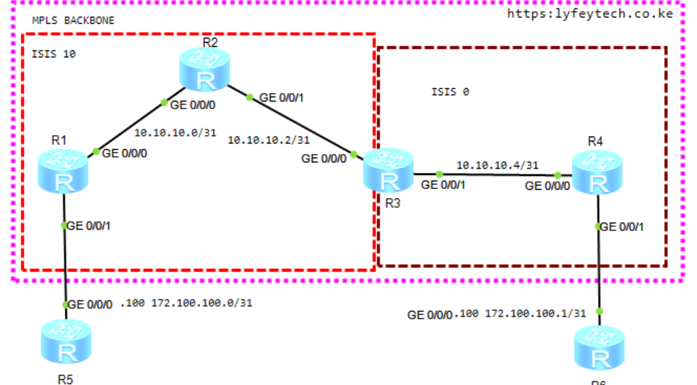
Step 1: Configure IP addresses on interfaces, and enable IS-IS and MPLS on interfaces in the MPLS backbone.
*******************************R1
sysname R1
#
mpls lsr-id 1.1.1.1
mpls
#
mpls l2vpn
#
mpls ldp
#
isis 10
 is-level level-2
 cost-style wide
 network-entity 49.0010.0010.0100.1001.00
 is-name R1
#
interface LoopBack0
 ip address 1.1.1.1 255.255.255.255
 isis enable 10
#
interface GigabitEthernet0/0/0
 ip address 10.10.10.0 255.255.255.254
 isis enable 10
 mpls
 mpls ldp
#
*******************************R2
sysname R2
#
mpls lsr-id 2.2.2.2
mpls
#
mpls l2vpn
#
mpls ldp
#
isis 10
is-level level-2
cost-style wide
network-entity 49.0010.0020.0200.2002.00
is-name R1
#
interface LoopBack0
ip address 2.2.2.2 255.255.255.255
isis enable 10
#
interface GigabitEthernet0/0/0
ip address 10.10.10.1 255.255.255.254
isis enable 10
mpls
mpls ldp
#
interface GigabitEthernet0/0/1
ip address 10.10.10.2 255.255.255.254
isis enable 10
mpls
mpls ldp
#*******************************R3
sysname R3
#
mpls lsr-id 3.3.3.3
mpls
#
mpls l2vpn
#
mpls ldp
#
isis 10
is-level level-2
cost-style wide
network-entity 49.0010.0030.0300.3003.00
is-name R3
import-route isis 20
#
isis 20
is-level level-2
cost-style wide
network-entity 49.0020.0030.0300.3003.00
is-name R3
import-route isis 10
#
interface LoopBack0
ip address 3.3.3.3 255.255.255.255
isis enable 20
#
interface GigabitEthernet0/0/0
ip address 10.10.10.3 255.255.255.254
isis enable 10
mpls
mpls ldp
#
interface GigabitEthernet0/0/1
ip address 10.10.10.4 255.255.255.254
isis enable 20
mpls
mpls ldp
#*******************************R4
sysname R4
#
mpls lsr-id 4.4.4.4
mpls
#
mpls l2vpn
#
mpls ldp
#
isis 20
is-level level-2
cost-style wide
network-entity 49.0020.0040.0400.4004.00
is-name R1
#
interface LoopBack0
ip address 4.4.4.4 255.255.255.255
isis enable 20
#
interface GigabitEthernet0/0/0
ip address 10.10.10.5 255.255.255.254
isis enable 20
mpls
mpls ldp
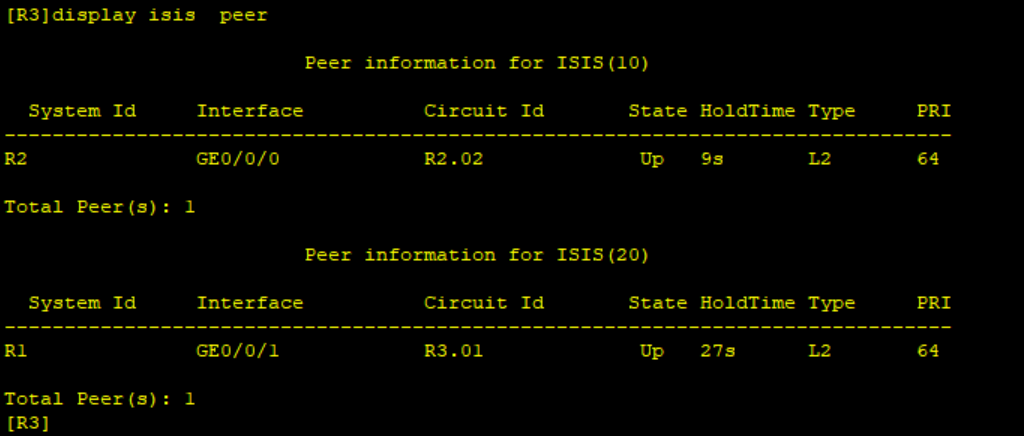
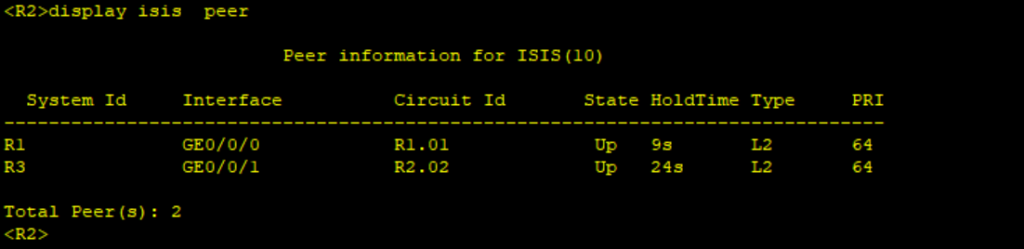
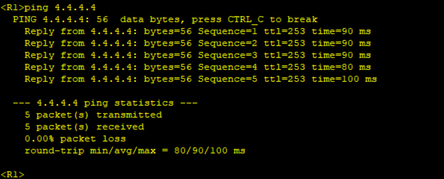
#Step 2: Verify IS-IS status in the MPLS backbone network. Verify R1 can ping R4 loopback address(4.4.4.4).
Step 3: Configure MPLS LDP remote peers between R1 and R3, R3 and R4.
************************R1
mpls ldp remote-peer 3.3.3.3
 remote-ip 3.3.3.3
#
************************R3
mpls ldp remote-peer 1.1.1.1
remote-ip 1.1.1.1
#
mpls ldp remote-peer 4.4.4.4
remote-ip 4.4.4.4
#************************R4
mpls ldp remote-peer 3.3.3.3
remote-ip 3.3.3.3
#Step 4: Configure a PWE3 between R1 and R4 on interfaces facing the CEs. We use 100 as the VC-ID on both R1 and R4.
********************************R1
#
interface GigabitEthernet0/0/1.100
 vlan-type dot1q 100
 mpls l2vc 3.3.3.3 100 raw
 mpls l2vc service-name 100
#
********************************R1
#
interface GigabitEthernet0/0/1.100
vlan-type dot1q 100
mpls l2vc 3.3.3.3 100 raw
mpls l2vc service-name 100
#Because R1 and R4 are in different IS-IS process, we need to configure our Pseudowire to switch on R3.
*****************************R3
mpls switch-l2vc 1.1.1.1 100 between 4.4.4.4 100 encapsulation ethernet
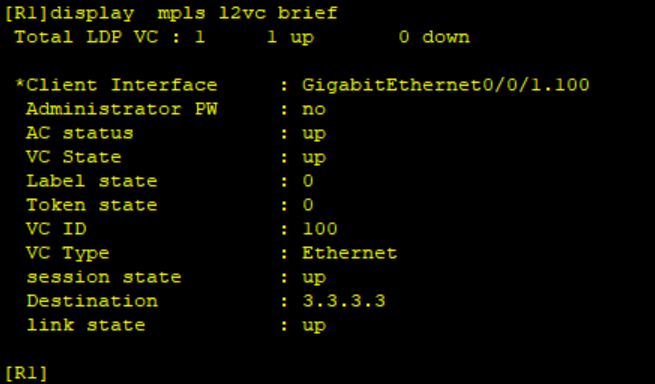
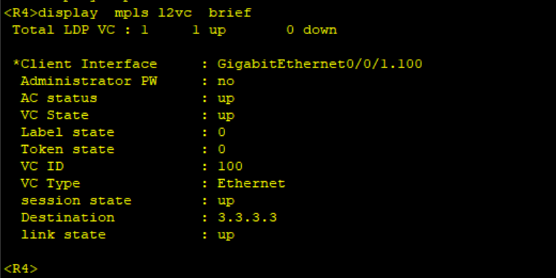
#Step 5: Verify status of PWE3 on R1 and R4.
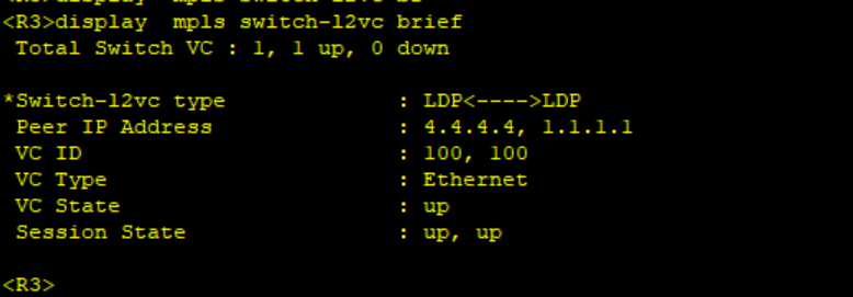
On R3, we can see the status of the switching as shown below:
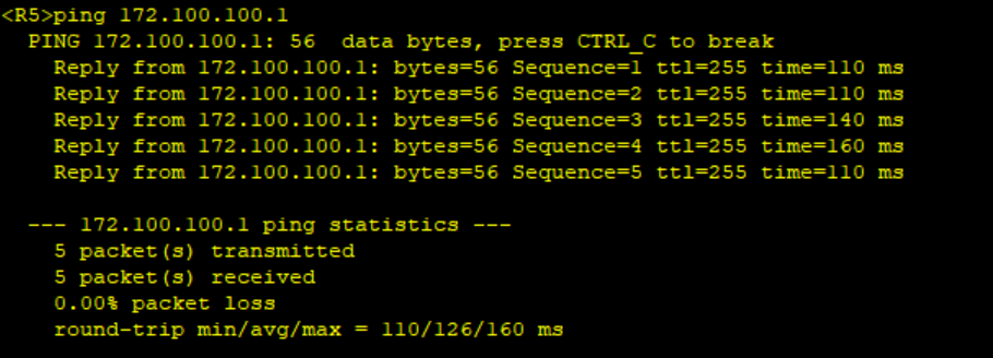
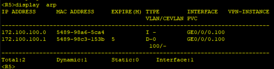
Step 6. Configure R5 and R6 and confirm connectivity over the PWE3.
*************************R5
#
interface GigabitEthernet0/0/0.100
 vlan-type dot1q 100
 ip address 172.100.100.0 255.255.255.254
#
*************************R6
#
interface GigabitEthernet0/0/0.100
 vlan-type dot1q 100
 ip address 172.100.100.1 255.255.255.254
#
Ping R6 IP address from R5 and verify the MAC address table of R5 and R6.
Thank you for reading our articles. Kindly leave your comments and also subscribe to our Youtube channel for more content on networking: Lyfey Technologies Youtube Channel
Related Posts
- Step by step guide on how to implement different networking protocols on Juniper MX routers
- L2 EVPN Implementation on Huawei Routers.
- VRRP Monitoring of the Uplink Interface status on Huawei routers.
- Association between VRRP and BFD Implementation on Huawei routers.
- Association between VRRP and STP Implementation on Huawei routers.
Leave a Reply
You must be logged in to post a comment.