
Implementing OSPF Virtual Links on Cisco Routers
- April 29, 2024
- Posted by: Lyfey Technologies
- Categories: Cisco, Networking
This article demonstrates how to configure OSPF Virtual links on Huawei devices: Implementing OSPF Virtual Links on Huawei Routers
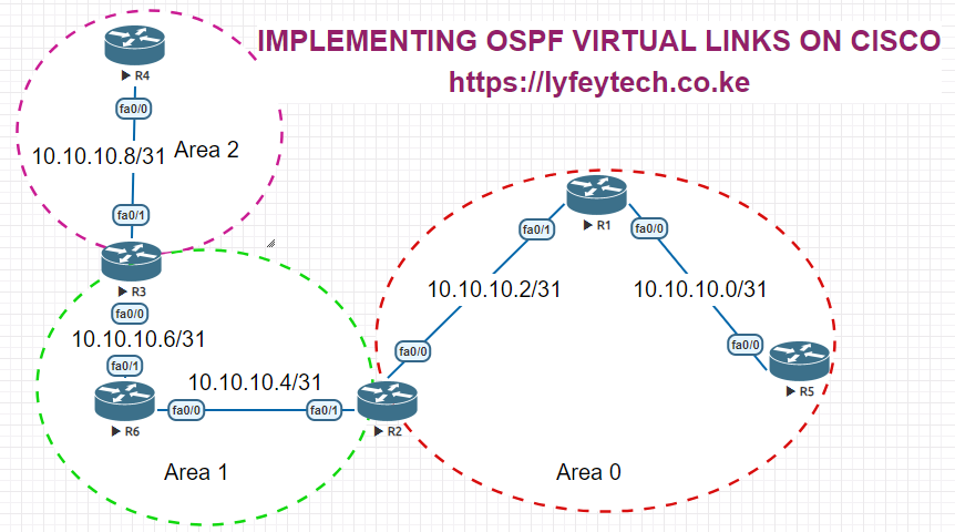
This lab focuses on how to implement OSPF virtual links on Cisco Routers.
Configuration Steps
Step 1: Configure IP addresses on the interfaces on all the routers.
************************R1
enable
config terminal
!
hostname R1
!
interface FastEthernet0/0
 ip address 10.10.10.0 255.255.255.254
 no shutdown
!
interface FastEthernet0/1
 ip address 10.10.10.2 255.255.255.254
 no shutdown
!
interface Loopback0
 ip address 1.1.1.1 255.255.255.255
!
************************R2
enable
config terminal
!
hostname R2
!
interface FastEthernet0/0
ip address 10.10.10.3 255.255.255.254
no shutdown
!
interface FastEthernet0/1
ip address 10.10.10.4 255.255.255.254
no shutdown
!
interface Loopback0
ip address 2.2.2.2 255.255.255.255
!************************R3
enable
config terminal
!
hostname R3
!
interface FastEthernet0/0
ip address 10.10.10.7 255.255.255.254
no shutdown
!
interface FastEthernet0/1
ip address 10.10.10.8 255.255.255.254
no shutdown
!
interface Loopback0
ip address 3.3.3.3 255.255.255.255
!************************R4
enable
config terminal
!
hostname R4
!
interface FastEthernet0/0
ip address 10.10.10.9 255.255.255.254
no shutdown
!
interface Loopback0
ip address 4.4.4.4 255.255.255.255
!************************R5
enable
config terminal
!
hostname R5
!
interface FastEthernet0/0
ip address 10.10.10.1 255.255.255.254
no shutdown
!
interface Loopback0
ip address 5.5.5.5 255.255.255.255
!************************R6
enable
config terminal
!
hostname R6
!
interface FastEthernet0/0
ip address 10.10.10.5 255.255.255.254
no shutdown
!
interface FastEthernet0/1
ip address 10.10.10.6 255.255.255.254
no shutdown
!
interface Loopback0
ip address 6.6.6.6 255.255.255.255
!Step 2: Configure OSPF on all the routers and advertise respective networks.
************************R1
!
router ospf 10
 router-id 1.1.1.1
 log-adjacency-changes
 network 1.1.1.1 0.0.0.0 area 0
 network 10.10.10.0 0.0.0.1 area 0
 network 10.10.10.2 0.0.0.1 area 0
!
************************R2
!
router ospf 10
router-id 2.2.2.2
log-adjacency-changes
network 2.2.2.2 0.0.0.0 area 0
network 10.10.10.4 0.0.0.1 area 1
network 10.10.10.2 0.0.0.1 area 0
!************************R3
!
router ospf 10
router-id 3.3.3.3
log-adjacency-changes
network 3.3.3.3 0.0.0.0 area 1
network 10.10.10.6 0.0.0.1 area 1
network 10.10.10.8 0.0.0.1 area 2
!************************R4
!
router ospf 10
router-id 4.4.4.4
log-adjacency-changes
network 4.4.4.4 0.0.0.0 area 2
network 10.10.10.8 0.0.0.1 area 2
!************************R5
!
router ospf 10
router-id 5.5.5.5
log-adjacency-changes
network 5.5.5.5 0.0.0.0 area 0
network 10.10.10.0 0.0.0.1 area 0
!************************R6
!
router ospf 10
router-id 6.6.6.6 3.3.3.3
log-adjacency-changes
network 6.6.6.6 0.0.0.0 area 1
network 10.10.10.6 0.0.0.1 area 1
network 10.10.10.4 0.0.0.1 area 1
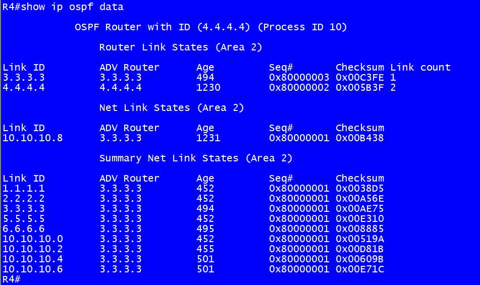
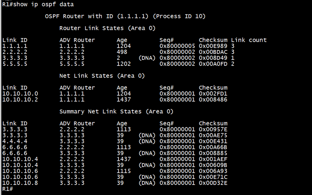
!Step 3: Verify OSPF peer adjacencies and LSDB on all routers as follows.
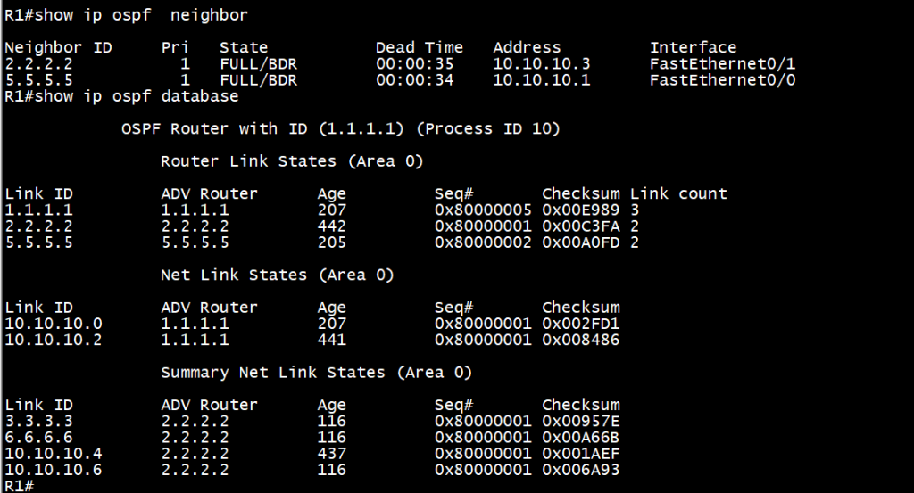
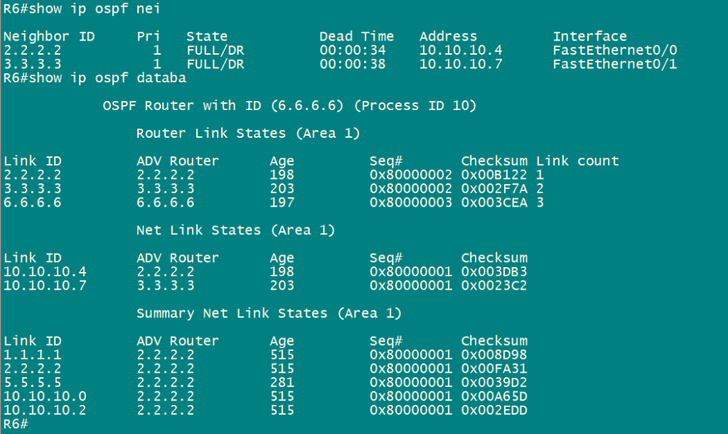
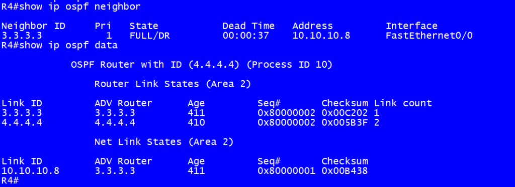
Note: R1 and R6 dont have any information from Area 2 in their LSDBs. Similarly, R4 doe not have any details or LSAs from Area 1 and Area 0. We need to configure a virtual link for Area 2 to connect to Area 0 for it to be able to get LSAs from Area 1 and Area 0.
Step 4: Configure a virtual link for Area 2 on R2 and R3 as follows.
**********************R2
!
router ospf 10
 area 1 virtual-link 3.3.3.3
!
**********************R3
!
router ospf 10
area 1 virtual-link 2.2.2.2
!Step 5: Verify Virtual links status and recheck LSDBs on routers.
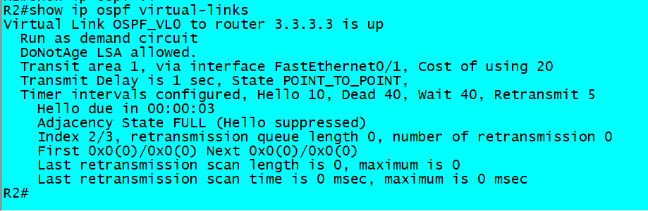
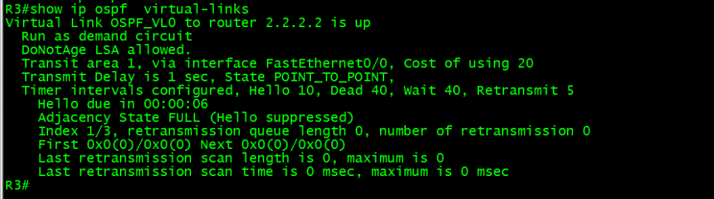
R1 now has LSAs from Area 2 in its LSDB. R4 also has LSA from Area 1 and Area 0 in its LSDB.
Thank you for reading our articles. Please check our website for more interesting content on networking.
Related Posts
- Step by step guide on how to implement different networking protocols on Juniper MX routers
- L2 EVPN Implementation on Huawei Routers.
- VRRP Monitoring of the Uplink Interface status on Huawei routers.
- Association between VRRP and BFD Implementation on Huawei routers.
- Association between VRRP and STP Implementation on Huawei routers.
Leave a Reply
You must be logged in to post a comment.