
Implementing OSPF Sham Link
- May 12, 2024
- Posted by: Lyfey Technologies
- Categories: Huawei, Networking
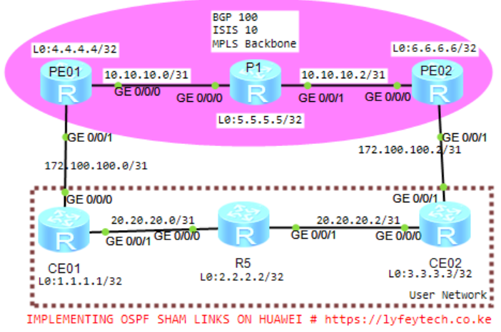
OSPF sham links are unnumbered P2P links between two PEs over an MPLS VPN backbone network.
On the BGP/MPLS IP VPN backbone network, if an intra-area OSPF link exists between the network segment where the local CE resides and the network segment where the remote CE resides, the route over this intra-area OSPF link is an intra-area route and has a higher priority than the inter-area route over the BGP/MPLS IP VPN backbone network. In this case, VPN traffic is always forwarded through this intra-area route. To prevent this problem, you can set up an OSPF sham link between the PEs so that the route over the MPLS IP VPN backbone network becomes an OSPF intra-area route and ensure that this route is preferentially selected.
Configuration Steps
Step 1: Configure Hostnames and IP addresses on all interfaces on all routers.
*************************CE01
sys
#
sysname CE01
#
interface GigabitEthernet0/0/0
 ip address 172.100.100.1 255.255.255.254
#
interface GigabitEthernet0/0/1
 ip address 20.20.20.0 255.255.255.254
#
interface LoopBack0
 ip address 1.1.1.1 255.255.255.255
#
*************************CE02
sys
#
sysname CE02
#
interface GigabitEthernet0/0/1
ip address 172.100.100.3 255.255.255.254
#
interface GigabitEthernet0/0/0
ip address 20.20.20.3 255.255.255.254
#
interface LoopBack0
ip address 3.3.3.3 255.255.255.255
#*************************R5
sys
#
sysname R5
#
interface GigabitEthernet0/0/0
ip address 20.20.20.1 255.255.255.254
#
interface GigabitEthernet0/0/1
ip address 20.20.20.2 255.255.255.254
#
interface LoopBack0
ip address 2.2.2.2 255.255.255.255
#*************************PE01
sys
#
sysname PE01
#
interface GigabitEthernet0/0/0
ip address 10.10.10.0 255.255.255.254
#
interface GigabitEthernet0/0/1
ip address 172.100.100.0 255.255.255.254
#
interface LoopBack0
ip address 4.4.4.4 255.255.255.255
#*************************P01
sys
#
sysname P01
#
interface GigabitEthernet0/0/0
ip address 10.10.10.1 255.255.255.254
#
interface GigabitEthernet0/0/1
ip address 10.10.10.2 255.255.255.254
#
interface LoopBack0
ip address 5.5.5.5 255.255.255.255
#*************************PE02
sys
#
sysname PE02
#
interface GigabitEthernet0/0/0
ip address 10.10.10.3 255.255.255.254
#
interface GigabitEthernet0/0/1
ip address 172.100.100.2 255.255.255.254
#
interface LoopBack0
ip address 6.6.6.6 255.255.255.255
#Step 2: Configure basic MPLS and LDP on interfaces on PE01, P01, and PE02 that are in the MPLS backbone.
************************PE01
mpls lsr-id 4.4.4.4
mpls
#
mpls ldp
#
interface GigabitEthernet0/0/0
 mpls
 mpls ldp
#
************************P01
mpls lsr-id 5.5.5.5
mpls
#
mpls ldp
#
interface GigabitEthernet0/0/0
mpls
mpls ldp
#
interface GigabitEthernet0/0/1
mpls
mpls ldp
#************************PE02
mpls lsr-id 6.6.6.6
mpls
#
mpls ldp
#
interface GigabitEthernet0/0/0
mpls
mpls ldp
#Step 3: Configure IGP(OSPF) in the MPLS Backbone.
************************PE01
#
ospf 10
 area 0.0.0.0
  network 4.4.4.4 0.0.0.0
  network 10.10.10.0 0.0.0.1
#
************************P01
#
ospf 10
area 0.0.0.0
network 5.5.5.5 0.0.0.0
network 10.10.10.0 0.0.0.1
network 10.10.10.2 0.0.0.1
#************************PE02
#
ospf 10
area 0.0.0.0
network 6.6.6.6 0.0.0.0
network 10.10.10.2 0.0.0.1
#Step 4: Configure OSPF on CE01, R5 and CE02.
*************************CE01
#
ospf 10 router-id 1.1.1.1
 area 0.0.0.0
  network 1.1.1.1 0.0.0.0
  network 20.20.20.0 0.0.0.1
  network 172.100.100.0 0.0.0.1
#
*************************CE02
#
ospf 10 router-id 3.3.3.3
area 0.0.0.0
network 3.3.3.3 0.0.0.0
network 20.20.20.2 0.0.0.1
network 172.100.100.2 0.0.0.1
#*************************R5
#
ospf 10 router-id 2.2.2.2
area 0.0.0.0
network 2.2.2.2 0.0.0.0
network 20.20.20.0 0.0.0.1
network 20.20.20.2 0.0.0.1
#Step 5: Configure MP-IBGP peering relationship between PE01 and PE02.
***********************PE01
bgp 100
 router-id 4.4.4.4
 peer 6.6.6.6 as-number 100
 peer 6.6.6.6 connect-interface LoopBack0
 #
 ipv4-family unicast
  undo peer 6.6.6.6 enable
 #
 ipv4-family vpnv4
  peer 6.6.6.6 enable
#
***********************PE02
bgp 100
router-id 6.6.6.6
peer 4.4.4.4 as-number 100
peer 4.4.4.4 connect-interface LoopBack0
#
ipv4-family unicast
undo peer 4.4.4.4 enable
#
ipv4-family vpnv4
peer 4.4.4.4 enable
#Step 6: Configure VRF on PEs and enable OSPF on the connections between PEs and CEs.Perform route import between BGP and OSPF.
***********************PE01
#
ip vpn-instance VRF1
 ipv4-family
  route-distinguisher 100:1
  vpn-target 100:100 export-extcommunity
  vpn-target 100:100 import-extcommunity
#
interface GigabitEthernet0/0/1
 ip binding vpn-instance VRF1
 ip address 172.100.100.0 255.255.255.254
#
ospf 100 vpn-instance VRF1
 import-route bgp
 domain-id 0.0.0.10
 area 0.0.0.0
  network 172.100.100.0 0.0.0.1
#
bgp 100
 ipv4-family vpn-instance VRF1
  import-route direct
  import-route ospf 100
#
***********************PE02
#
ip vpn-instance VRF1
ipv4-family
route-distinguisher 100:1
vpn-target 100:100 export-extcommunity
vpn-target 100:100 import-extcommunity
#
interface GigabitEthernet0/0/1
ip binding vpn-instance VRF1
ip address 172.100.100.2 255.255.255.254
#
ospf 100 vpn-instance VRF1
import-route bgp
domain-id 0.0.0.10
area 0.0.0.0
network 172.100.100.2 0.0.0.1
#
bgp 100
ipv4-family vpn-instance VRF1
import-route direct
import-route ospf 100
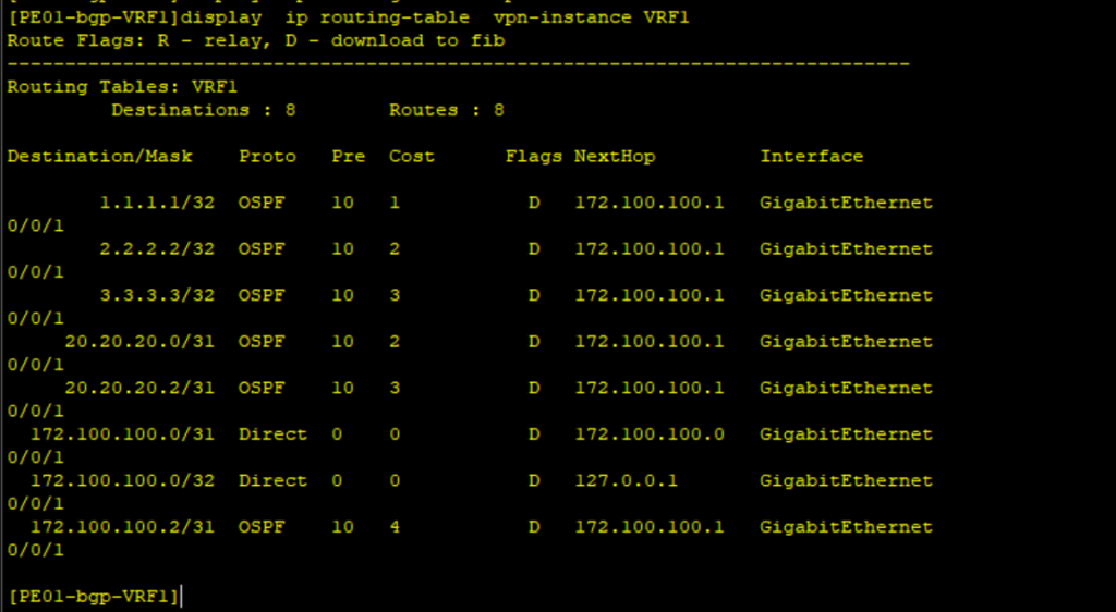
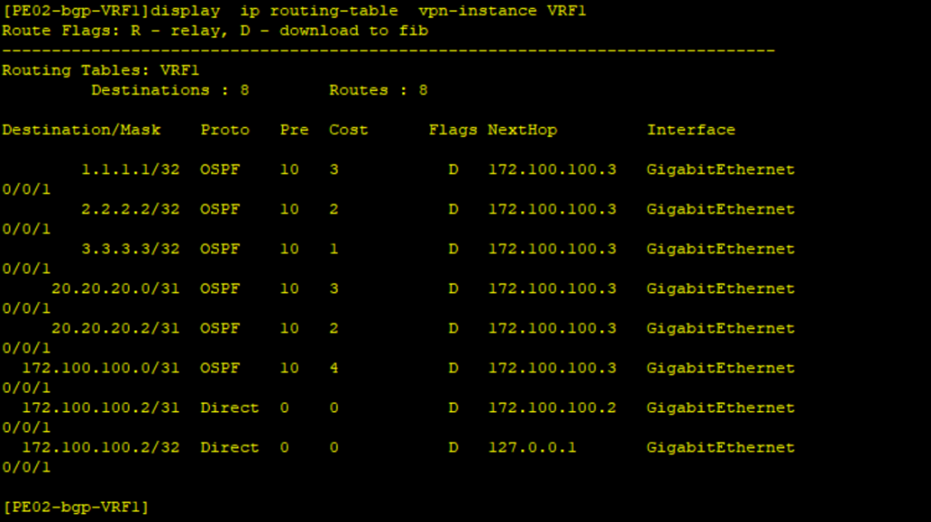
#Step 7: Check the routing table on PEs for VRF1.
The route to the CEs from PEs are OSPF routes over the CE network(user network) rather than the BGP route over the backbone network. This can be fixed by deploying OSPF sham links. The traffic to remote CEs should flow through the backbone MPLS network.
Step 8: Configure OSPF Sham links on PE01 and PE02.
**************************PE01
ospf 100 vpn-instance VRF1
 area 0.0.0.0
  sham-link 7.7.7.7 8.8.8.8 cost 10
#
**************************PE02
ospf 100 vpn-instance VRF1
area 0.0.0.0
sham-link 8.8.8.8 7.7.7.7 cost 10
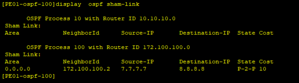
#Step 9: Verify the status of the OSPF Sham link.
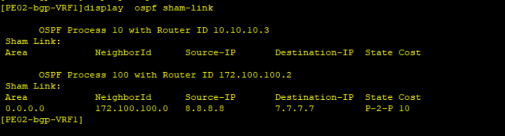
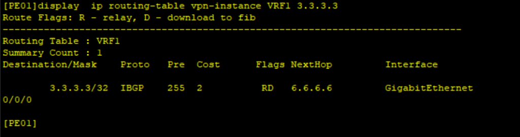
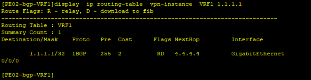
Step 10: Check the routing table of PE01 and PE02 for routes to remote CEs.
The traffic to remote CEs is through the MPLS backbone.
Thank you for reading our articles. Check out other interesting articles on our blog and leave your comments below.
Latest Posts
- Step by step guide on how to implement different networking protocols on Juniper MX routers
- L2 EVPN Implementation on Huawei Routers.
- VRRP Monitoring of the Uplink Interface status on Huawei routers.
- Association between VRRP and BFD Implementation on Huawei routers.
- Association between VRRP and STP Implementation on Huawei routers.
Leave a Reply
You must be logged in to post a comment.