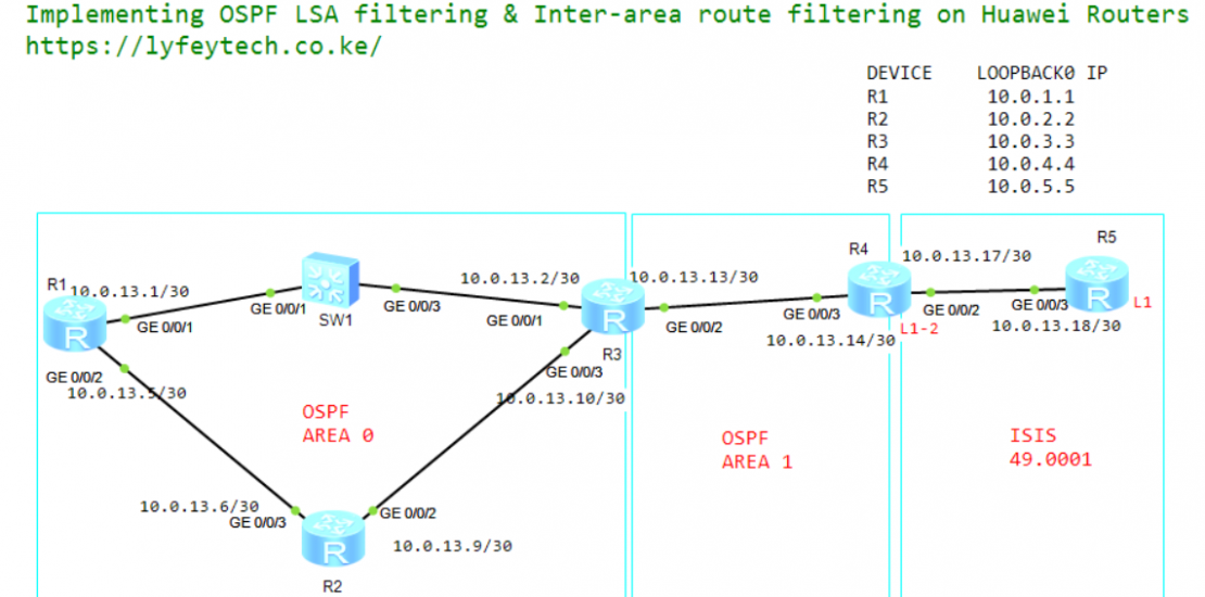
There are four AR routers running OSPF on the intranet. To control the number of OSPF LSDBs, the four AR routers are assigned to different areas. IS-IS runs between R4 (ASBR) in OSPF area 1 and R5 in the branch. To control the number of routes on the headquarters network, route filtering is configured on R3 (ABR) to limit the number of routes that can enter OSPF area 0. The branch needs to access the headquarters network. The network administrator has delivered the default IS-IS routes to the branch instead of importing OSPF routes to the 1S-IS routing table.
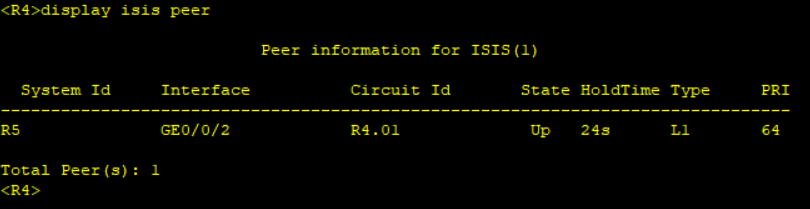
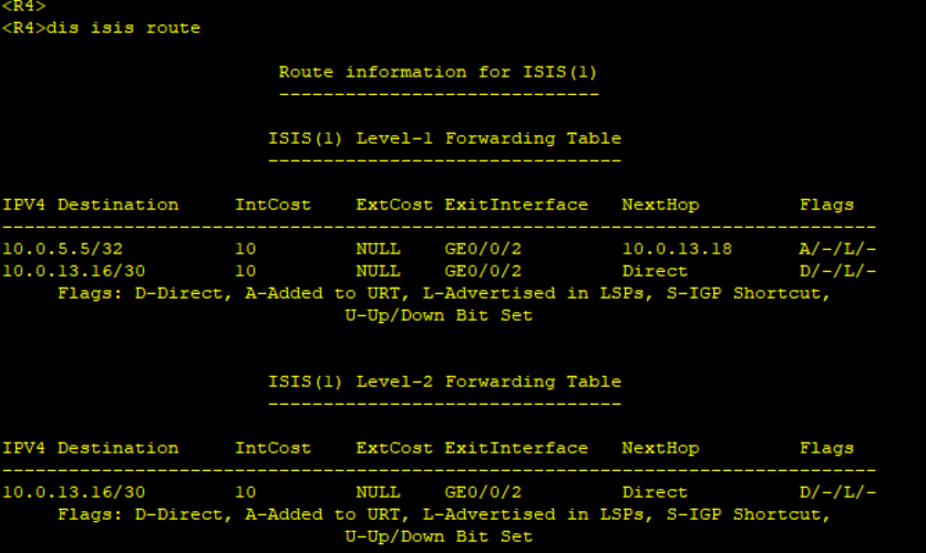
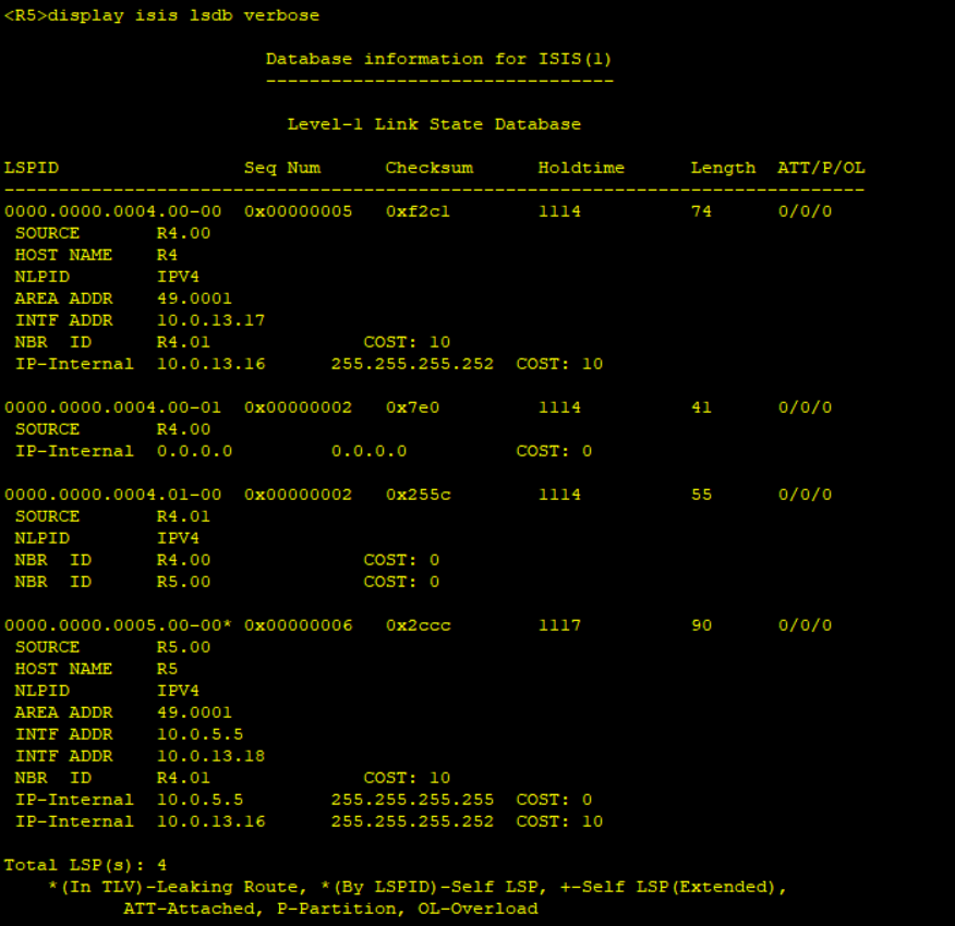
Check the ISIS neighbor relationship and IS-IS routing table on R4
Step 4: Configure OSPF route control.
On R1 and R2, create Loopback2 interfaces on R1 and R2 and assign IP addresses on network segment 172:16.2.1/24 to Loopback2 interfaces. Activate OSPF on Loopback2 interfaces and set the number of equal-cost routes to 1 on R3. On R4, create the loopback 3 interface with the IP address on network segment 172.16.3.1/24, change the OSPF interface type to broadcast, activate OSPF on the Loopback3 interface, and perform inter-area Type 3 LSA filtering on R3 (ABR) to prevent the OSPF inter-area route 172.16.3.0/24 from being transmitted to OSPF area 0.
Create loopback 2 interfaces on R1 and R2 and activate OSPF on the two interfaces
*******************************************R1
interface loopBack2
ip address 172.16.2.1 32
ospf enable 1 area 0
#

*******************************************R2
interface loopBack2
ip address 172.16.2.1 32
ospf enable 1 area 0
#
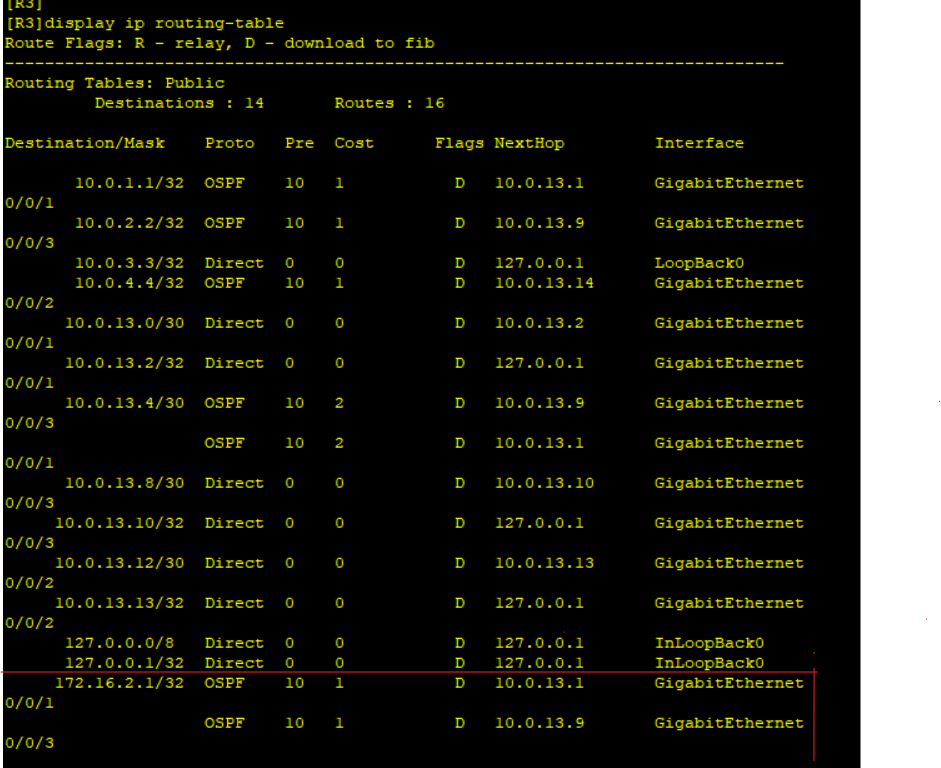
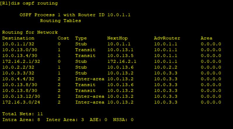
Check the OSPF routing table of R3
The OSPF route 172.16.2.1/32 is used for load balancing, with R1 and R2 as next hops.
Set the maximum number of equal-cost routes for load balancing to 1 on R3
*******************************************R3
ospf 1
maximum load-balancing 1
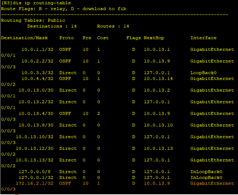
Check the routing table on R3 again.
There is only one OSPF route 172.16.2.1/32 on R3, and the next hop is R2. When the number of equal-cost routes is greater than number specified in the maximum load-balancing command, valid routes are selected for load balancing based on the following criteria: Route priority: Routes with the highest priority (lowest weight) are selected for load balancing. Interface index: If routes have the same priority, the routes with the largest interface index are selected for load balancing. Next-hop IP address: If routes have the same priority and interface index, the routes with the largest next-hop IP addresses are selected for load balancing. The index of GE0/0/3 on R3 connected to R2 is greater than that of GEO/0/1 on R1, so the OSPF route 172.16.2.1/32 from R2 becomes valid.
Create LoopBack3 on R4 and activate OSPF
*******************************************R4
interface loopBack2
ip address 172.16.3.1 24
ospf enable 1 area 1
ospf network-type broadcast
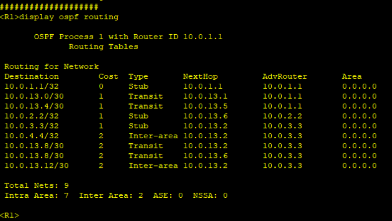
Check OSPF routing information on R1
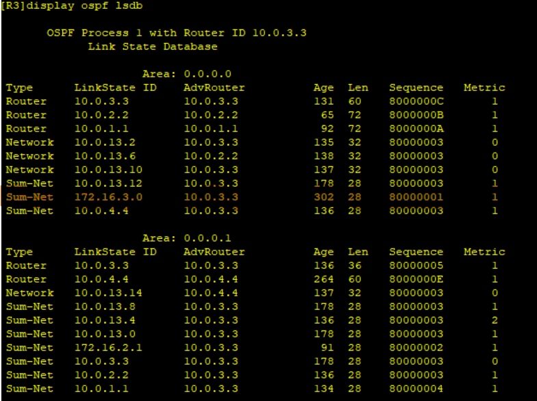
Check OSPF LSDB on R3
Configure Type 3 LSA filtering on R3 (ABR) to prevent the OSPF inter-area route 172.16.3.0/24 from being transmitted to OSPF area 0.
*******************************************R3
ip ip-prefix 1 index 10 deny 172.16.3.0 24 greater-equal 24 less-equal 24
ip ip-prefix 1 index 20 permit 0.0.0.0 0 less-equal 32

ospf 1
area 1
filter ip-prefix 1 export
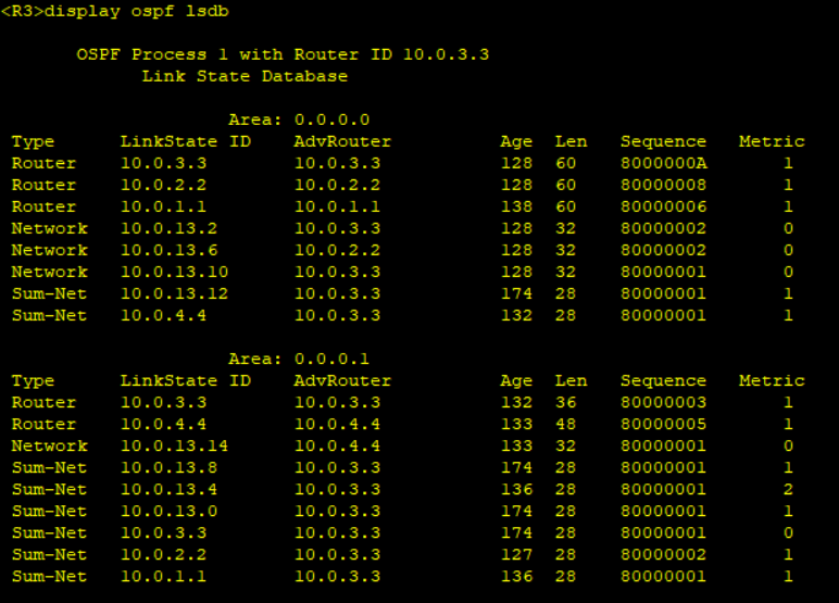
Check OSPF LSB on R3 again.
The Type 3 LSA 172.16.3.0 cannot be found in the LSDB of OSPF area 0 on R3.
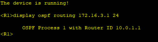
Check the OSPF route 172.16.3.1/24 route on R1
OSPF route 172.16.3.1/24 route does not exist on R1
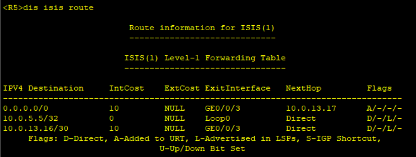
Step 5: Configure default IS-IS route control.
Advertise the default route on R4 and check whether the default route is generated on R5.
I’m Amelia Rose, working at Cryptopredic where we bring you simple, clear and insightful crypto predictions. I’ll bookmark your site and take the feeds additionally? I am happy to find so many helpful info right here in the submit, we’d like develop more strategies in this regard, thank you for sharing

I’m Amelia Rose, working at Cryptopredic where we bring you simple, clear and insightful crypto predictions. I’ll bookmark your site and take the feeds additionally? I am happy to find so many helpful info right here in the submit, we’d like develop more strategies in this regard, thank you for sharing