
Implementing MUX VLAN on Huawei Switches
- May 26, 2024
- Posted by: James Majani
- Categories: Huawei, Networking
Basic Concepts
MUX VLANs are classified into principle VLANs and subordinate VLANS. Subordinate VLANs are further classified into separate and group VLANs. 1. Principal VLAN-interfaces in principal VLAN can communicate with all interfaces in a MUX VLAN. 2. Subordinate VLAN-divided into: a) Separate VLAN-a separate interface can communicate only with a principal interface and is isolated from other types of interfaces. Each separate VLAN must be bound to a principal VLAN. b) Group VLAN-a group interface can communicate with a principal interface and the other interfaces in the same group, but cannot communicate with interfaces in other group VLANS or a separate VLAN. Each group VLAN must be bound to a principal VLAN.
Networking Description
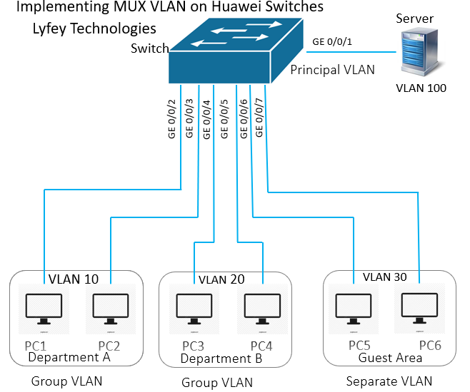
On a switch, VLANs of departments A and B are configured as subordinate group VLANs, the VLAN of the guest area is configured as a subordinate separate VLAN, and the VLAN of the interface connected to the server is configured as the principal VLAN. In addition, all the subordinate VLANs are bound to the principal VLAN. In this way, the following network design requirements are met:
• PCs in department A can communicate with each other at Layer 2.
• PCs in department B can communicate with each other at Layer 2.
• Hosts in departments A and B are isolated at Layer 2.
• Employees in departments A and B can access the server at Layer 2.
• Any PC in the guest area can access only the server and cannot access any other devices, including other guests.
Configure VLAN 100 as the principal VLAN, VLAN 10 and VLAN 20 as group VLANs, VLAN 30 as a separate VLAN and add interfaces to related VLANs and enable MUX VLAN function.
Step 1: Configure VLAN parameters on the Access Switch
*******************************************ACC_1                                             system-view
sysname ACC_1
vlan batch 10 20 30 100
VLAN 100
mux-vlan
subordinate group 10 20
subordinate separate 30

interface GigabitEthernet 0/0/1
 port link-type access
 port default vlan 100
 port mux-vlan enable
  #
interface GigabitEthernet 0/0/2
 port link-type access
 port default vlan 10
 port mux-vlan enable
  #
interface GigabitEthernet 0/0/3
 port link-type access
 port default vlan 10
 port mux-vlan enable
  #
interface GigabitEthernet 0/0/4
 port link-type access
 port default vlan 20
 port mux-vlan enable
  #
interface GigabitEthernet 0/0/5
 port link-type access
 port default vlan 20
 port mux-vlan enable
  #
interface GigabitEthernet 0/0/6
 port link-type access
 port default vlan 30
 port mux-vlan enable
  #
interface GigabitEthernet 0/0/7
 port link-type access
 port default vlan 30
 port mux-vlan enable
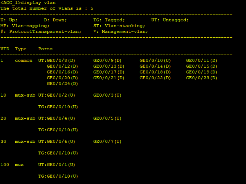
Step 2: Result Verification: Check VLAN status on ACC_1.
Step 4: Configure IP addresses for PCs and Servers based on the table below.
| Server | 192.168.1.1/26 |
| PC1 | 192.168.1.65/26 |
| PC2 | 192.168.1.66/26 |
| PC3 | 192.168.1.129/26 |
| PC4 | 192.168.1.130/26 |
| PC5 | 192.168.1.193/26 |
| PC6 | 192.168.1.194/26 |
Step 4: Test communication between PCs: in the same group VLAN, in different group VLAN and in same separate VLAN.
Ping PC2 from PC1. Ping PC3 from PC1. Ping PC6 from PC5.
Leave a Reply
You must be logged in to post a comment.