
Implementing Generic Routing Encapsulation (GRE) on Huawei routers.
- June 30, 2024
- Posted by: James Majani
- Category: Huawei
Basic Concepts.
GRE encapsulates data packets and redirects them to a device that decapsulates them and routes them to their final destination. This allows the source and destination switches to operate as if they have a virtual point-to-point connection with each other, because the outer header applied by GRE is transparent to the encapsulated payload packet. For example, GRE tunnels allow routing protocols such as RIP, IS-IS, OSPF and BGP to forward data packets from one switch to another switch across the Internet. In addition, GRE tunnels can encapsulate multicast data streams for transmission over the Internet.
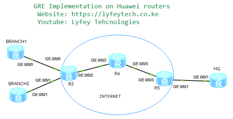
Networking Description.
As shown in our topology, HQ router, BRANCH1 and BRANCH2 routers, are gateways of the enterprise headquarters and branches. The service provider has allocated a public network IP address to each gateway and the gateways can communicate with each other.
The enterprise requires a simple cost-effective mechanism to implement communication between the headquarters and branches through private networks. Generic Routing Encapsulation (GRE) tunnels can be established between the headquarters and branches to meet this requirement.
In this environment, BGP is used in the backbone network, between BRANCH1, BRANCH2 and Internet router (R3) BGP is used to exchange Public IPS of the gateways across the Internet. Between HQ router and Internet router (R5) OSPF protocol is configured to create routing entries. Static routes are configured on GWs for LAN-side reachability with the next hope as tunnel interface address on the gateways.
Step 1: Basic configurations.
*******************************************BRANCH1
system-view
sysname BRANCH1
#
interface GigabitEthernet0/0/0
 ip address 10.1.0.2 255.255.255.252
#
interface LoopBack0
 ip address 192.168.1.1 255.255.255.0

*******************************************BRANCH2
system-view
sysname BRANCH2
#
interface GigabitEthernet0/0/1
 ip address 10.2.0.2 255.255.255.252
#
interface LoopBack0
 ip address 192.168.2.1 255.255.255.0
#

*******************************************R3
system-view
sysname R3
#
interface GigabitEthernet0/0/0
 ip address 10.1.0.1 255.255.255.252
#
interface GigabitEthernet0/0/1
 ip address 10.2.0.1 255.255.255.252
#
interface GigabitEthernet0/0/2
 ip address 172.16.1.1 255.255.255.252


*******************************************R4
system-view
sysname R4
#
interface GigabitEthernet0/0/2
 ip address 172.16.1.2 255.255.255.252
#
interface GigabitEthernet0/0/3
 ip address 172.16.2.2 255.255.255.252
#
system-view

*******************************************R5
sysname R5
#
interface GigabitEthernet0/0/1
 ip address 10.3.0.1 255.255.255.252
#
interface GigabitEthernet0/0/3
 ip address 172.16.2.1 255.255.255.252

*******************************************HQ
system-view
sysname HQ
#
interface GigabitEthernet0/0/0
#
interface GigabitEthernet0/0/1
 ip address 10.3.0.2 255.255.255.252
#
interface LoopBack0
 ip address 192.168.3.1 255.255.255.0
Step 2: Configure BGP in the Internet Backbone, BGP between BRANCH1, BRANCH2 and R3, and OSPF between R5 and HQ router.
*******************************************BRANCH1
bgp 100
 peer 10.1.0.1 as-number 300
 #
 ipv4-family unicast
  undo synchronization
  network 10.1.0.0 255.255.255.252
  peer 10.1.0.1 enable

*******************************************BRANCH2
bgp 200
 peer 10.2.0.1 as-number 300
 #
 ipv4-family unicast
  undo synchronization
  network 10.2.0.0 255.255.255.252
  peer 10.2.0.1 enable

*******************************************R3
bgp 300
 peer 10.1.0.2 as-number 100
 peer 10.2.0.2 as-number 200
 peer 172.16.1.2 as-number 400
 #
 ipv4-family unicast
  undo synchronization
  import-route direct
  import-route static
  peer 10.1.0.2 enable
  peer 10.2.0.2 enable
  peer 172.16.1.2 enable

*******************************************R4
bgp 400
 peer 172.16.1.1 as-number 300
 peer 172.16.2.1 as-number 500
 #
 ipv4-family unicast
  undo synchronization
  import-route direct
  import-route static
  peer 172.16.1.1 enable
  peer 172.16.2.1 enable

*******************************************R5
bgp 500
 peer 172.16.2.2 as-number 400
 #
 ipv4-family unicast
  undo synchronization
  import-route direct
  import-route static
  import-route ospf 1
  peer 172.16.2.2 enable
#
ospf 1
 import-route bgp
 area 0.0.0.0
  network 10.3.0.0 0.0.0.3

*******************************************HQ
ospf 1
 area 0.0.0.0
  network 10.3.0.0 0.0.0.3
Step 3: Check BGP and OSPF neighbor relationships and the routing tables.
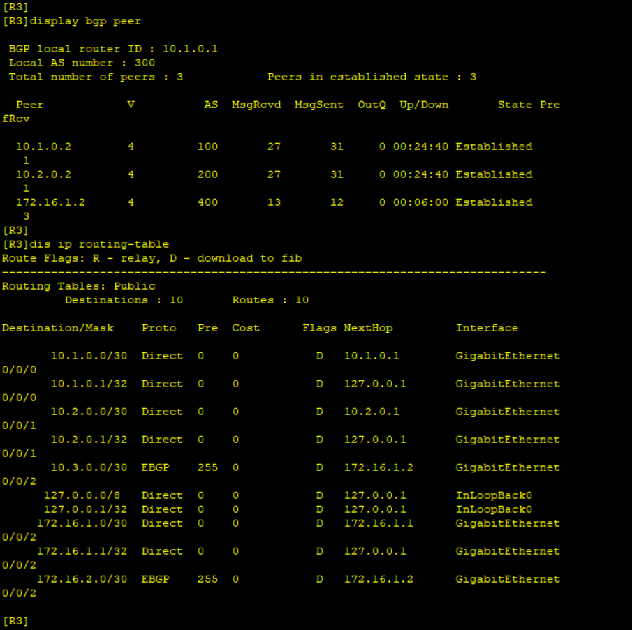
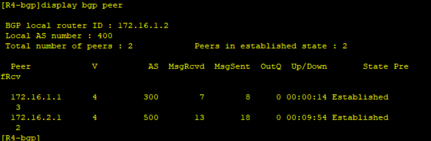
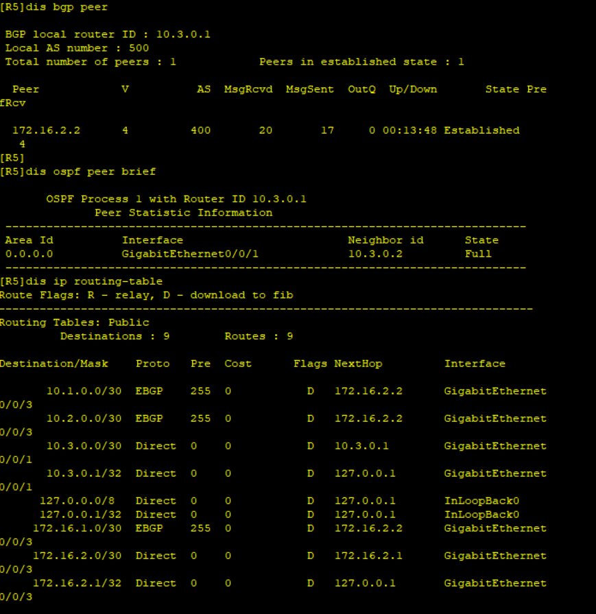
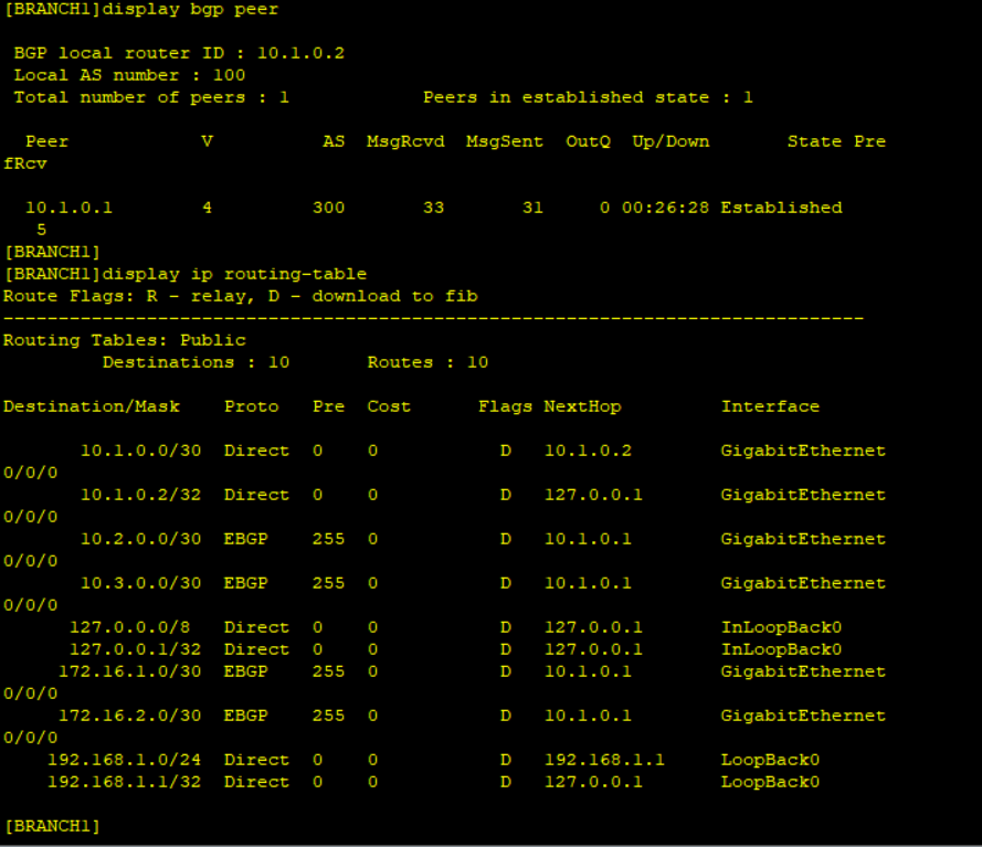
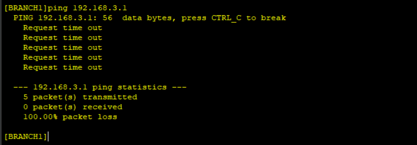
BGP and OPSF neighbor relationship is successful and the routers have exchanged WAN routes. No LAN routes are advertised and Ping from Branch to HQ’s Loopback0 fails.
Step 4: Configure GRE tunnel source Interfaces on BRANCH and HQ routers and static routes for LAN-side routes reachability.
*******************************************BRANCH1
interface Tunnel0/0/1
ip address 1.1.1.1 255.255.255.248
tunnel-protocol gre
source 10.1.0.2
destination 10.3.0.2
#
ip route-static 192.168.3.0 255.255.255.0 1.1.1.3
*******************************************BRANCH2
interface Tunnel0/0/1
ip address 1.1.2.2 255.255.255.248
tunnel-protocol gre
source 10.2.0.2
destination 10.3.0.2
#
ip route-static 192.168.3.0 255.255.255.0 1.1.2.3
*******************************************HQ
interface Tunnel0/0/1
ip address 1.1.1.3 255.255.255.248
tunnel-protocol gre
source 10.3.0.2
destination 10.1.0.2
#
interface Tunnel0/0/2
ip address 1.1.2.3 255.255.255.248
tunnel-protocol gre
source 10.3.0.2
destination 10.2.0.2
#
ip route-static 192.168.1.0 255.255.255.0 1.1.1.1
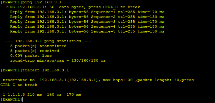
ip route-static 192.168.2.0 255.255.255.0 1.1.2.2Step 5: Check tunnel information and IP routing table of HQ and test LAN-side reachability of BRANCH and HQ.
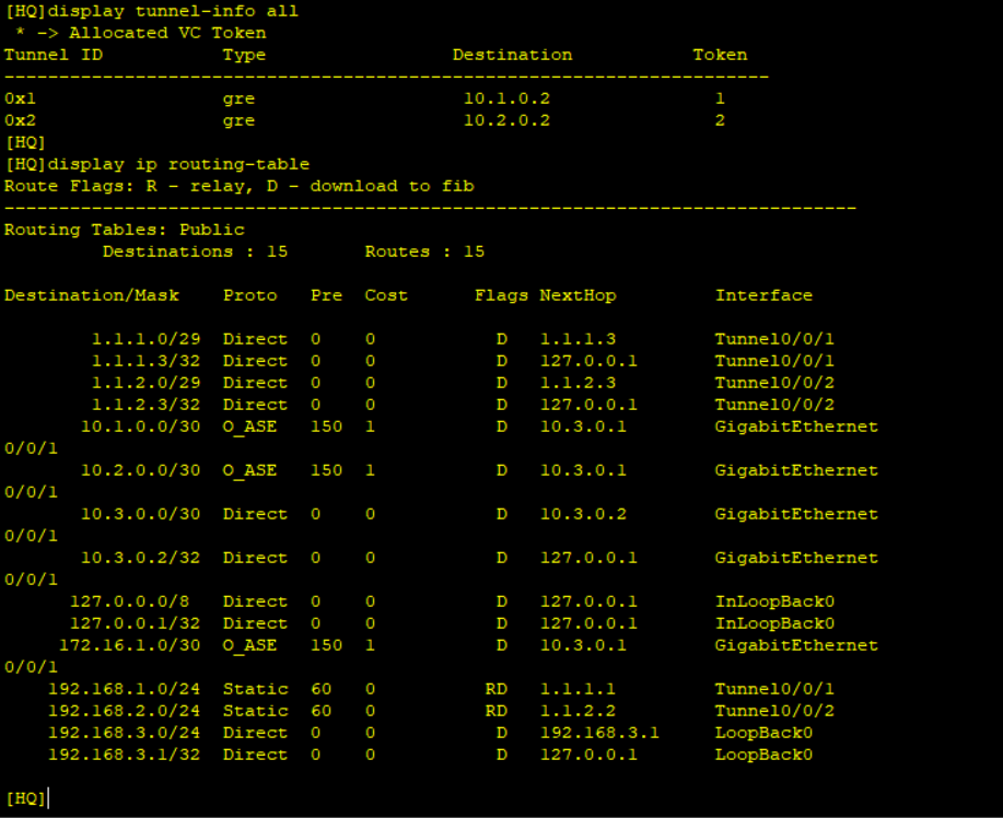
Traffic is routed to the GRE endpoint over routes established in the routing table. These routes can be statically configured or dynamically learned by routing protocols, in this case we used static routes. When a data packet is received by the GRE endpoint, it is decapsulated and routed again to its destination address.
GRE tunnels are stateless-–that is, the endpoint of the tunnel contains no information about the state or availability of the remote tunnel endpoint. Therefore, the switch operating as a tunnel source router cannot change the state of the GRE tunnel interface to down if the remote endpoint is unreachable.
Capture packets to check the packet composition.
Leave a Reply
You must be logged in to post a comment.