
Implementing BFD and FRR on Huawei Routers
- March 17, 2024
- Posted by: James Majani
- Category: Networking
Bidirectional Forwarding Detection (BFD) is a universal, standard, media-independent, and protocol-independent fast fault detection mechanism. BFD for OSPF associates BFD with OSPF. If a fault occurs on the link between a device and its neighbor, BFD can rapidly detect the link fault to speed up OSPF’s response to network topology change.
OSPF IP Fast Reroute (FRR) is a dynamic IP FRR technology that uses the loop-free alternate (LFA) to pre-calculate a backup path and save it in the forwarding table. If the primary link fails, traffic is rapidly switched to the backup link, ensuring traffic continuity and achieving traffic protection.
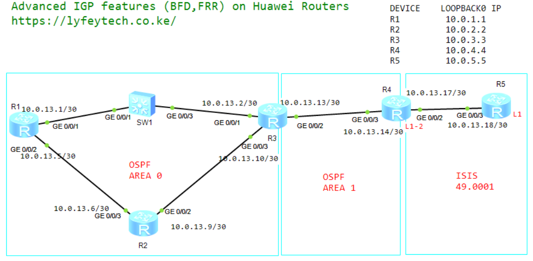
There are four routers running OSPF on the intranet. To control the number of OSPF LSDBs, the four AR routers are assigned to different areas. IS-IS runs between R4 (ASBR) in OSPF area 1 and R5 in the branch.
To speed up OSPF convergence, the network administrator deploys OSPF IP FRR and the association between OSPF and BFD.
Step 1: Configure IP addresses for Devices.
*******************************************R1
system-view
sysname R1

interface GigabitEthernet 0/0/1
description TO_SW1_GE 0/0/1
ip address 10.0.13.1 30
#
interface GigabitEthernet 0/0/2
description TO_R2_GE 0/0/3
ip address 10.0.13.5 30
#
interface LoopBack0
ip address 10.0.1.1 255.255.255.255
#
*******************************************R2
system-view
sysname R2

interface GigabitEthernet 0/0/3
description TO_R1_GE 0/0/2
ip address 10.0.13.6 30
#
interface GigabitEthernet 0/0/2
description TO_R3_GE 0/0/3
ip address 10.0.13.9 30
#
interface LoopBack0
ip address 10.0.2.2 255.255.255.255
#
*******************************************R3
system-view
sysname R3

interface GigabitEthernet 0/0/1
description TO_SW1_GE 0/0/3
ip address 10.0.13.2 30
#
interface GigabitEthernet 0/0/2
description TO_R4_GE 0/0/3
ip address 10.0.13.13 30
#
interface GigabitEthernet 0/0/3
description TO_R2_GE 0/0/2
ip address 10.0.13.10 30
#
interface LoopBack0
ip address 10.0.3.3 255.255.255.255
#
*******************************************R4
system-view
sysname R4
interface GigabitEthernet 0/0/3
description TO_R3_GE 0/0/2
ip address 10.0.13.14 30
#
interface GigabitEthernet 0/0/2
description TO_R5_GE 0/0/3
ip address 10.0.13.17 30
#
interface LoopBack0
ip address 10.0.4.4 255.255.255.255
#*******************************************R5
system-view
sysname R5
interface GigabitEthernet 0/0/3
description TO_R4_GE 0/0/2
ip address 10.0.13.18 30
#
interface LoopBack0
ip address 10.0.5.5 255.255.255.255
#Step 2: Configure OSPF according to the planning.
*******************************************R1
ospf 1 router-id 10.0.1.1
area 0
network 10.0.13.0 0.0.0.3
network 10.0.13.4 0.0.0.3
network 10.0.1.1 0.0.0.0
*******************************************R2
ospf 1 router-id 10.0.2.2
area 0
network 10.0.13.8 0.0.0.3
network 10.0.13.4 0.0.0.3
network 10.0.2.2 0.0.0.0
*******************************************R3
ospf 1 router-id 10.0.3.3
area 0
network 10.0.13.0 0.0.0.3
network 10.0.13.8 0.0.0.3
network 10.0.3.3 0.0.0.0
#
area 1
network 10.0.13.12 0.0.0.3*******************************************R4
ospf 1 router-id 10.0.4.4
area 1
network 10.0.13.12 0.0.0.3
network 10.0.4.4 0.0.0.0
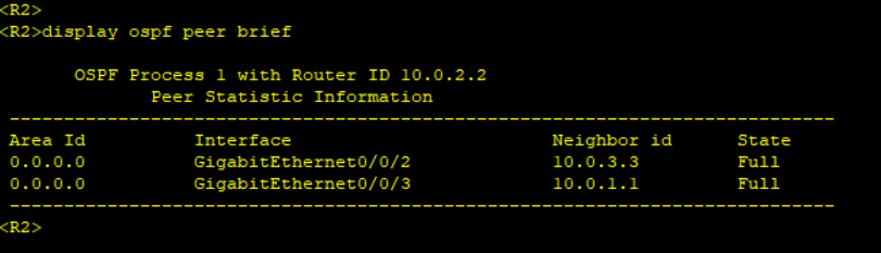
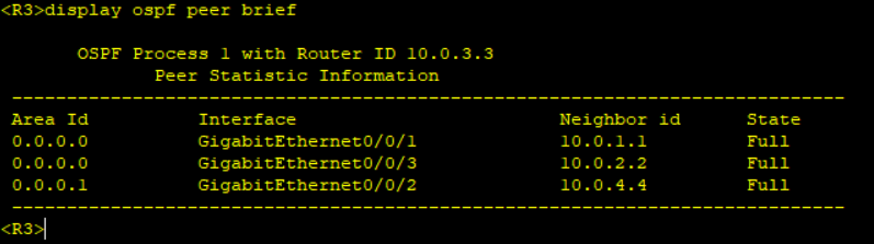
Check the OSPF neighbor relationship status on R2 and R3.
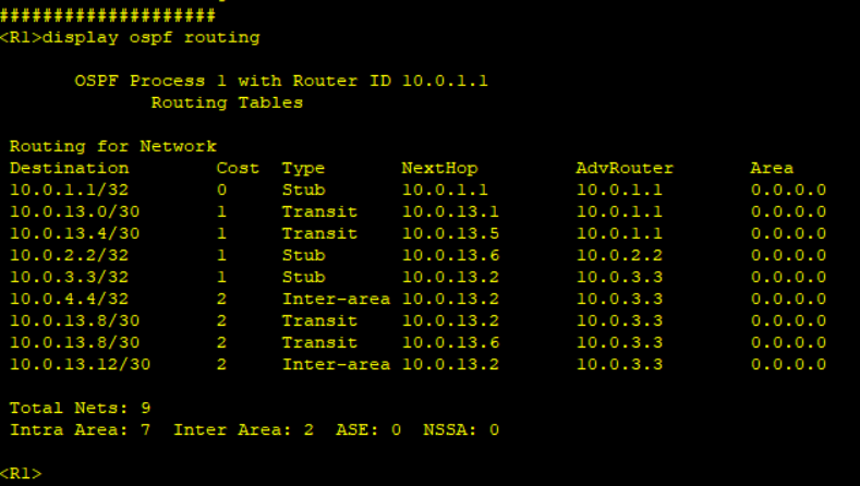
Check the OSPF routing table on R1
Step 3: Configure IS-IS according to the planning
*******************************************R4
isis 1
is-level level-1-2
is-name R4
network-entity 49.0001.0000.0000.0004.00
#
int GigabitEthernet 0/0/2
isis enable 1
#
*******************************************R5
isis 1
is-level level-1
is-name R5
network-entity 49.0001.0000.0000.0005.00
#
int GigabitEthernet 0/0/3
isis enable 1
#
int LoopBack 0
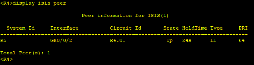
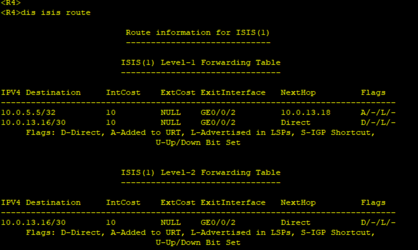
isis enable 1Check the ISIS neighbor relationship and IS-IS routing table on R4
An IS-IS level-1 neighbor relationship has been established between R4 and R5.
R4 has learnt the route to loopback0 of R5.
Step 4: Configure OSPF FRR
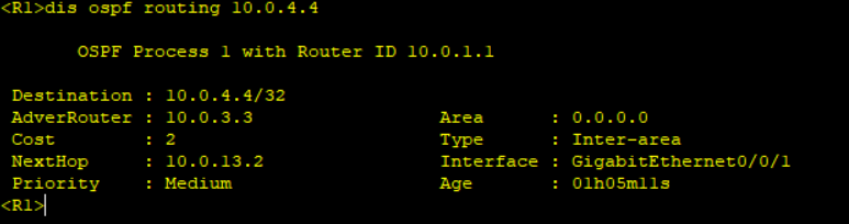
Check the OSPF route to 10.0.4.4/32 on R1
In this case the next hop to 10.0.4.4/32 id 10.0.13.2
Enable FRR on R1
*******************************************R1
ospf 1
frr
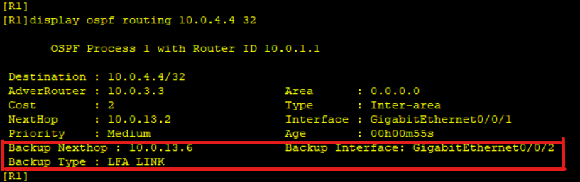
loop-free-alternateCheck the OSPF route 10.0.4.4/32 on R1
A backup route destined for R4’s LoopBack0 interface has been generated on R1, with the next hop address being 10.0.13.6 and outbound interface being GE0/0/2. The backup route is destined for R4’s Loopback0 interface through R2
Step 5: Configure BFD
Enable BFD globally on R1, R2, R3 and R4.
*******************************************R1
bfd
#
ospf 1
bfd all-interfaces enable
*******************************************R2
bfd
#
ospf 1
bfd all-interfaces enable
*******************************************R3
bfd
#
ospf 1
bfd all-interfaces enable
*******************************************R4
bfd
#
ospf 1
bfd all-interfaces enable
Configure BFD on R2,R3, and R4, set the minimum intervals for sending and receiving packets to 500ms, and the local detection multiplier to 4.
*******************************************R1
interface GigabitEthernet 0/0/1
ospf bfd enable
ospf bfd min-tx-interval 500 min-rx-interval 500 detect-multiplier 4
#
interface GigabitEthernet 0/0/2
ospf bfd enable
ospf bfd min-tx-interval 500 min-rx-interval 500 detect-multiplier 4
*******************************************R2
interface GigabitEthernet 0/0/2
ospf bfd enable
ospf bfd min-tx-interval 500 min-rx-interval 500 detect-multiplier 4
#
interface GigabitEthernet 0/0/3
ospf bfd enable
ospf bfd min-tx-interval 500 min-rx-interval 500 detect-multiplier 4*******************************************R3
interface GigabitEthernet 0/0/1
ospf bfd enable
ospf bfd min-tx-interval 500 min-rx-interval 500 detect-multiplier 4
#
interface GigabitEthernet 0/0/2
ospf bfd enable
ospf bfd min-tx-interval 500 min-rx-interval 500 detect-multiplier 4
#
interface GigabitEthernet 0/0/3
ospf bfd enable
ospf bfd min-tx-interval 500 min-rx-interval 500 detect-multiplier 4
*******************************************R4
interface GigabitEthernet 0/0/3
ospf bfd enable
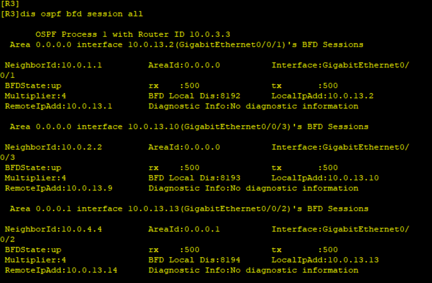
ospf bfd min-tx-interval 500 min-rx-interval 500 detect-multiplier 4Check the BFD session status on R3
Shutdown GE0/0/1 of R3 and test the association between BFD and FRR
*******************************************R3
interface GigabitEthernet 0/0/1
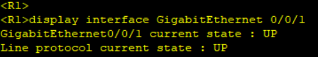
shutdownCheck the status of GigabitEthernet 0/0/1 on R1
R1 and R3 are connected through SW1. After GE0/0/1 on R3 is shut down, GE0/0/1 on R1 is still Up and cannot detect the connectivity interruption between R1 and R3.
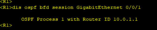
Check the BFD session status on GE0/0/1 of R1.
There is no BFD session
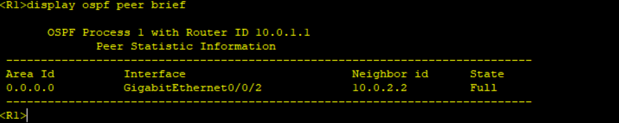
Check the OSPF neighbor relationship status on R1.
The OSPF neighbor relationship between R1 and R3 has been terminated, and the time of shutting down GE0/0/1 on R3 is smaller than the OSPF dead interval.
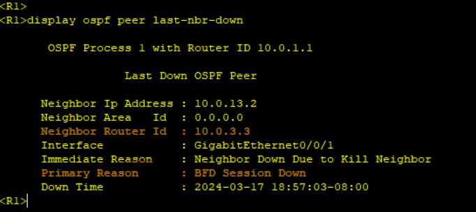
Check on R1 the reason why the neighbor relationship is interrupted.
The command output shows that the neighbor relationship between R1 and R3 is interrupted because the BFD session is Down.
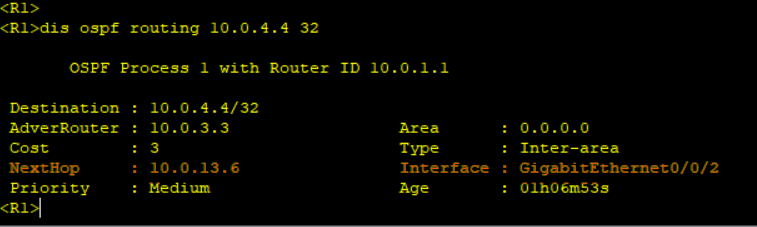
Check OSPF route 10.0.4.4/32 on R1
The next hop of the route to R4’s LoopBack0 interface is changed to 10.0.13.6, and the outbound interface is GE0/0/2
Related Posts
- Step by step guide on how to implement different networking protocols on Juniper MX routers
- L2 EVPN Implementation on Huawei Routers.
- VRRP Monitoring of the Uplink Interface status on Huawei routers.
- Association between VRRP and BFD Implementation on Huawei routers.
- Association between VRRP and STP Implementation on Huawei routers.
397 Comments
Leave a Reply
You must be logged in to post a comment.
Good job.
[…] Implementing BFD and FRR on Huawei Routers […]