
Implementation of Pseudo wire on Huawei Routers.
- April 3, 2024
- Posted by: Lyfey Technologies
- Categories: Huawei, Networking
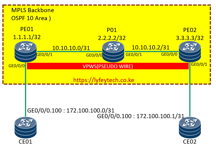
This lab simulates how to configure a Pseudo Wire which is a layer 2 VPN on Huawei routers. As shown in the topology above, we have PE01, P01, and PE02 routers in our MPLS backbone network and two CEs connecting to PE01 and PE02.
The lab objective is to configure an L2VPN from PE01 to PE02 on VLAN 100 and ensure CE01 and CE02 can communicate through the L2VPN.
VC-ID should be the same on both PE01 and PE02. The L2VPN will not be up if the VC-ID is misconnfigured with different IDs.
Configuration Steps
Step 1: configure system names and MPLS on PE01, PE02 and P01.
*************************PE01
#
sysname PE01
#
mpls lsr-id 1.1.1.1
mpls
#
mpls l2vpn
#
mpls ldp
#
********************************P01
#
sysname P1
#
mpls lsr-id 2.2.2.2
mpls
#
mpls l2vpn
#
mpls ldp
#***************************PE02
#
sysname PE02
#
mpls lsr-id 3.3.3.3
mpls
#
mpls l2vpn
#
mpls ldp
#Step 2: Configure interfaces on PE01, P01 and PE02. Enable mpls and MPLS LDP on all interfaces in the MPLS backbone.
***************************PE01
interface GigabitEthernet0/0/1
 ip address 10.10.10.0 255.255.255.254
 mpls
 mpls ldp
#
****************************P01
#
interface GigabitEthernet0/0/0
ip address 10.10.10.1 255.255.255.254
mpls
mpls ldp
#
interface GigabitEthernet0/0/1
ip address 10.10.10.2 255.255.255.254
mpls
mpls ldp
#***************************PE02
#
interface GigabitEthernet0/0/0
ip address 10.10.10.3 255.255.255.254
mpls
mpls ldp
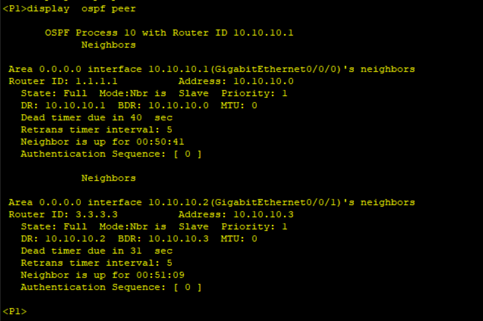
#Step 3: Configure OSPF in the MPLS Backbone and confirm the adjacency status.
*************************PE01
#
ospf 10 router-id 1.1.1.1
 area 0.0.0.0
  network 10.10.10.0 0.0.0.1
  network 1.1.1.1 0.0.0.0
#
****************************P01
#
ospf 10
area 0.0.0.0
network 2.2.2.2 0.0.0.0
network 10.10.10.0 0.0.0.1
network 10.10.10.2 0.0.0.1
#*****************************PE02
#
ospf 10 router-id 3.3.3.3
area 0.0.0.0
network 10.10.10.2 0.0.0.1
network 3.3.3.3 0.0.0.0
#
Step 4: Configure MPLS remote LDP session between PE01 and PE02 and verify the status.
*******************************PE01
#
mpls ldp remote-peer 3.3.3.3
 remote-ip 3.3.3.3
#
*******************************PE02
#
mpls ldp remote-peer 1.1.1.1
remote-ip 1.1.1.1
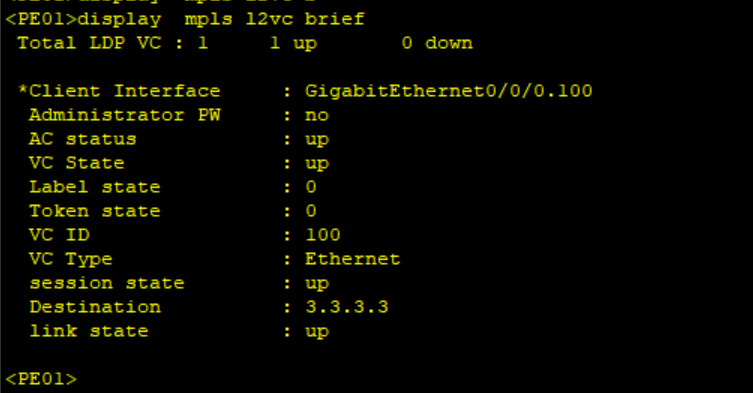
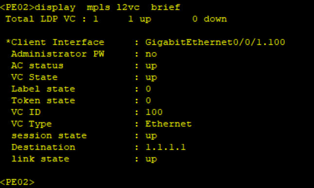
#Step 5: Configure PWE3( Pseudowire) between PE01 and PE02 on interfaces facing CEs. Use 100 as the VC-ID on both PEs. Verify VC status.
*******************************PE01
#
interface GigabitEthernet0/0/0.100
 vlan-type dot1q 100
 mpls l2vc 3.3.3.3 100 raw
 mpls l2vpn service-name 100
#
*****************************PE02
#
interface GigabitEthernet0/0/1.100
vlan-type dot1q 100
mpls l2vc 1.1.1.1 100 raw
mpls l2vpn service-name 100
#
Step 6: Configure CEs.
*****************************CE01
sysname CE01
#
interface GigabitEthernet0/0/0.100
 vlan-type dot1q 100
 ip address 172.100.100.0 255.255.255.254
#
***************************CE02
sysname CE02
#
interface GigabitEthernet0/0/0.100
vlan-type dot1q 100
ip address 172.100.100.1 255.255.255.254
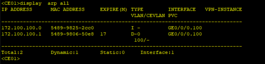
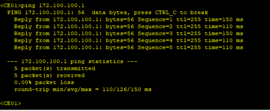
#Step 7: Verify communication between CEs.
392 Comments
Leave a Reply
You must be logged in to post a comment.
I am following your blogs regularly as i always get something for learning.
I will please to see config of L2 EVPN.
Thank you
Hello Basit. PWE3 is an example of L2VPN.
[…] our last article, we demonstrated how to configure an L2VPN on routers within the same IGP domain: Implementation of PWE3 on Huawei Routers. Today’s article demonstrates how to configure a Pseudowire on routers in different IGP […]