
Example of Configuring OSPF Virtual link on Huawei
- February 3, 2024
- Posted by: lyfey admin
- Categories: Huawei, Networking
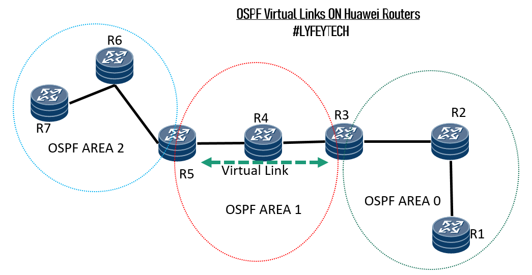
What are OSPF Virtual Links?
When designing an OSPF network, it is a requirement that all OSPF areas should be connected to the backbone area 0. In some implementations, it’s impossible to have a physical connection from a remote area to area 0. An OSPF virtual link can be applied in two scenarios.
- To connect the remote area to the backbone through a non-backbone area.
- Virtual links can also be used to connect two parts of a partitioned backbone through a non-backbone area.
Note: The area through which you configure the virtual link, known as a transit area, must have full routing information, hence the transit area cannot be a stub area.
Lab setup and Configuration Steps: In this article we focus on the first application of virtual links. The Objective is to connect Area 2 to backbone Area 0 using OSPF virtual links.
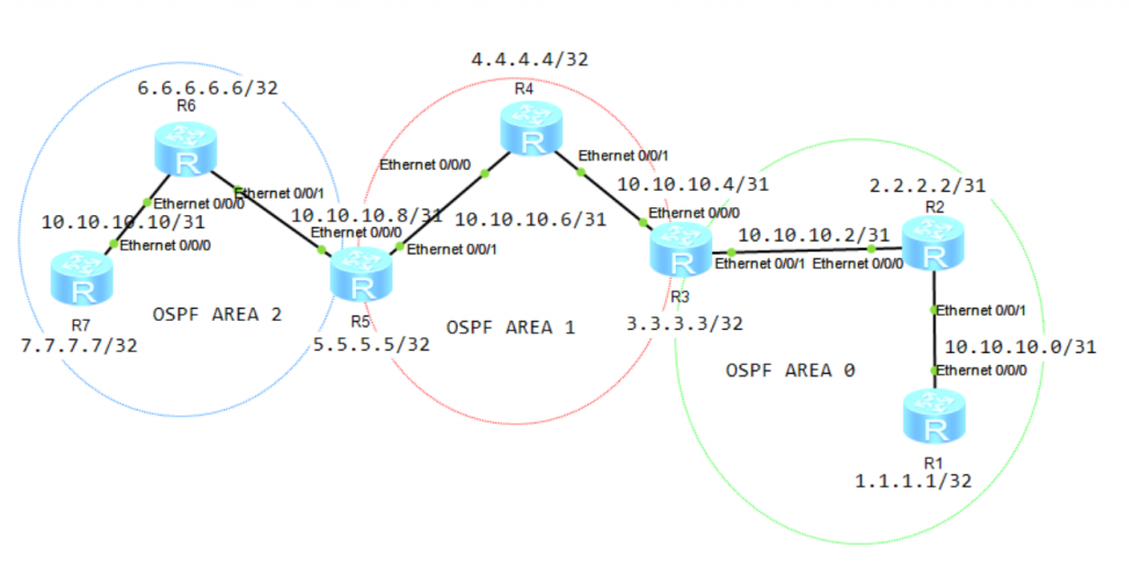
Step 1: Configure system names and IP addresses on all the routers.
*****************************************R1
sys
#
sysname R1
#
router id 1.1.1.1
#
interface Loopback0
ip address 1.1.1.1 32
#
interface Ethernet 0/0/0
description TO_R2_ETH/0/01
ip address 10.10.10.0 31
#
commit
*****************************************R2
sys
#
sysname R2
#
router id 2.2.2.2
#
interface Loopback0
ip address 2.2.2.2 32
#
interface Ethernet 0/0/1
description TO_R1_ETH/0/0/0
ip address 10.10.10.1 31
#
interface Ethernet 0/0/0
description TO_R1_ETH/0/0/0
ip address 10.10.10.2 31
#
commit
*****************************************R3
sys
#
sysname R3
#
router id 3.3.3.3
#
interface Loopback0
ip address 3.3.3.3 32
#
interface Ethernet 0/0/0
description TO_R4_ETH/0/0/0
ip address 10.10.10.4 31
#
interface Ethernet 0/0/1
description TO_R2_ETH/0/0/0
ip address 10.10.10.3 31
#
commit*****************************************R4
sys
#
sysname R4
#
router id 4.4.4.4
#
interface Loopback0
ip address 4.4.4.4 32
#
interface Ethernet 0/0/0
description TO_R5_ETH/0/0/1
ip address 10.10.10.6 31
#
interface Ethernet 0/0/1
description TO_R3_ETH/0/0/0
ip address 10.10.10.5 31
#
commit*****************************************R5
sys
#
sysname R5
#
router id 5.5.5.5
#
interface Loopback0
ip address 5.5.5.5 32
#
interface Ethernet 0/0/0
description TO_R6_ETH/0/0/1
ip address 10.10.10.8 31
#
interface Ethernet 0/0/1
description TO_R4_ETH/0/0/0
ip address 10.10.10.7 31
#
commit*****************************************R6
sys
#
sysname R6
#
router id 6.6.6.6
#
interface Loopback0
ip address 6.6.6.6 32
#
interface Ethernet 0/0/0
description TO_R7_ETH/0/0/1
ip address 10.10.10.10 31
#
interface Ethernet 0/0/1
description TO_R5_ETH/0/0/0
ip address 10.10.10.9 31
#
commit*****************************************R7
sys
#
sysname R7
#
router id 7.7.7.7
#
interface Loopback0
ip address 7.7.7.7 32
#
interface Ethernet 0/0/0
description TO_R6_ETH/0/0/0
ip address 10.10.10.11 31
#
commit
Step 2: Configure OSPF on all the routers and advertise the networks in respective areas.
*************************************R1
#
ospf 10 router-id 1.1.1.1
 area 0.0.0.0
  network 1.1.1.1 0.0.0.0
  network 10.10.10.0 0.0.0.1
  network 10.10.10.2 0.0.0.1
  network 3.3.3.2 0.0.0.1
#
commit
************************************R2
#
ospf 10
area 0.0.0.0
network 10.10.10.0 0.0.0.1
network 10.10.10.2 0.0.0.1
network 2.2.2.2 0.0.0.0
#************************************R3
#
ospf 10
area 0.0.0.0
network 10.10.10.2 0.0.0.1
network 3.3.3.3 0.0.0.0
area 0.0.0.1
network 10.10.10.4 0.0.0.1
#
commit
************************************R4
#
ospf 10
area 0.0.0.1
network 4.4.4.4 0.0.0.0
network 10.10.10.4 0.0.0.1
network 10.10.10.6 0.0.0.1
#
commit************************************R5
#
ospf 10
area 0.0.0.1
network 5.5.5.4 0.0.0.1
network 10.10.10.6 0.0.0.1
area 0.0.0.2
network 10.10.10.8 0.0.0.1
#************************************R6
#
ospf 10
area 0.0.0.2
network 6.6.6.6 0.0.0.0
network 10.10.10.8 0.0.0.1
network 10.10.10.10 0.0.0.1
#
commit************************************R7
#
ospf 10
area 0.0.0.2
network 7.7.7.7 0.0.0.0
network 10.10.10.10 0.0.0.1
#
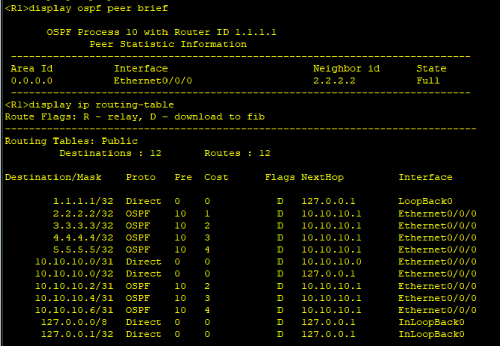
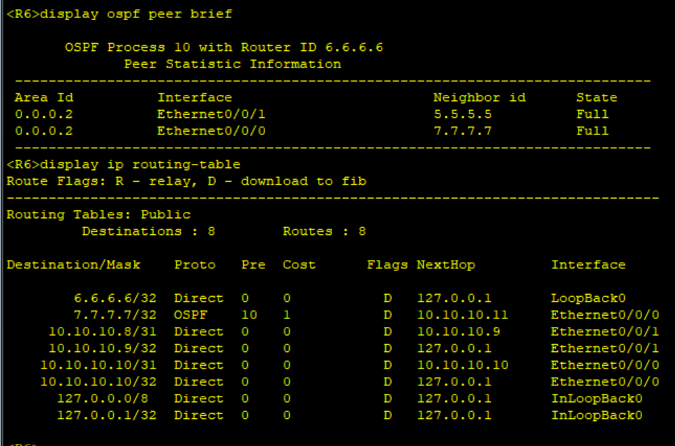
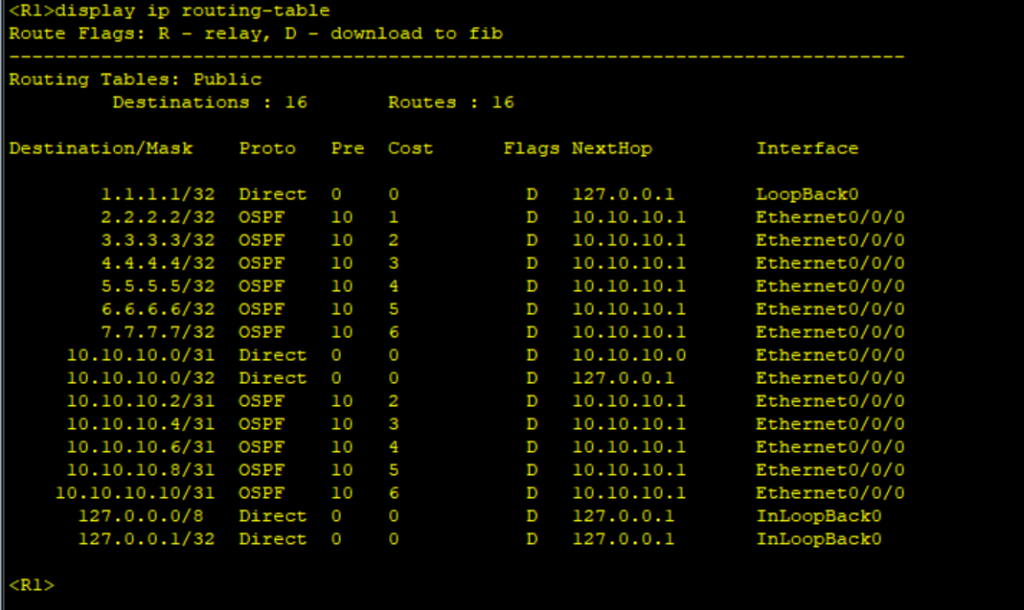
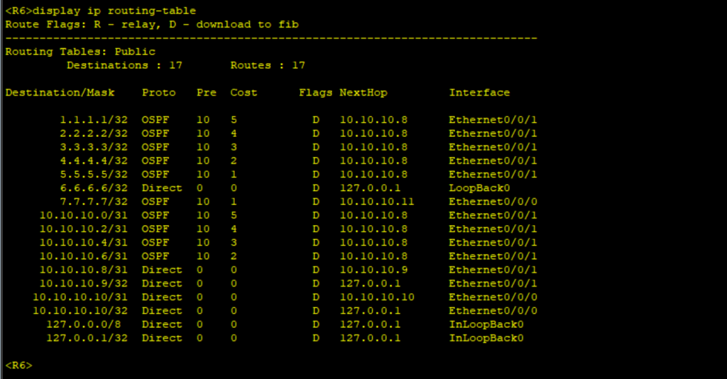
commitStep 3: Check OSPF adjacency status and routing tables on all the routers.
Step 4: Configure OSPF Virtual Links on R5 and R3. Area 1 is our transit area.
************************************R3
#
ospf 10
 area 0.0.0.1
  vlink-peer 5.5.5.5
#
commit
************************************R5
#
ospf 10
area 0.0.0.1
vlink-peer 3.3.3.3
#
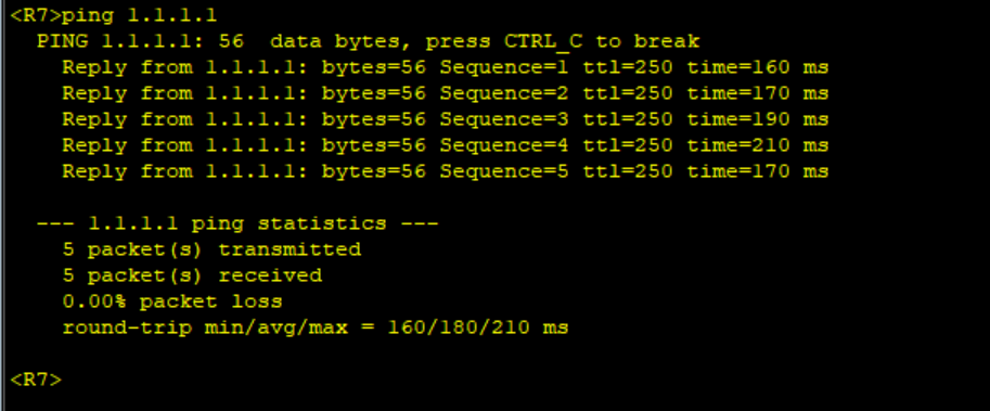
commitStep 5: Verify OSPF virtual link status between R3 and R5 using the command “dispay ospf vlink”. Recheck the routing table of R1 and R6. We are now able to exchange the routing information over the virtual link.

389 Comments
Leave a Reply
You must be logged in to post a comment.
[…] Example of Configuring OSPF Virtual link on Huawei […]