
BGP MPLS IP VPN Hub and Spoke implementation on Huawei routers
- March 3, 2024
- Posted by: James Majani
- Categories: Huawei, Networking
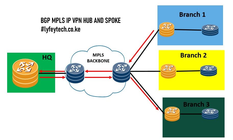
Hub and Spoke architecture is a network design where we have a central site ( Hub site) that is connected to multiple remote sites (Spokes), Spokes can communicate with each other directly or centrally through the Hub site. In this lab we simulate how we can achieve communication between Branches through HQ i.e. Hub and Spoke.
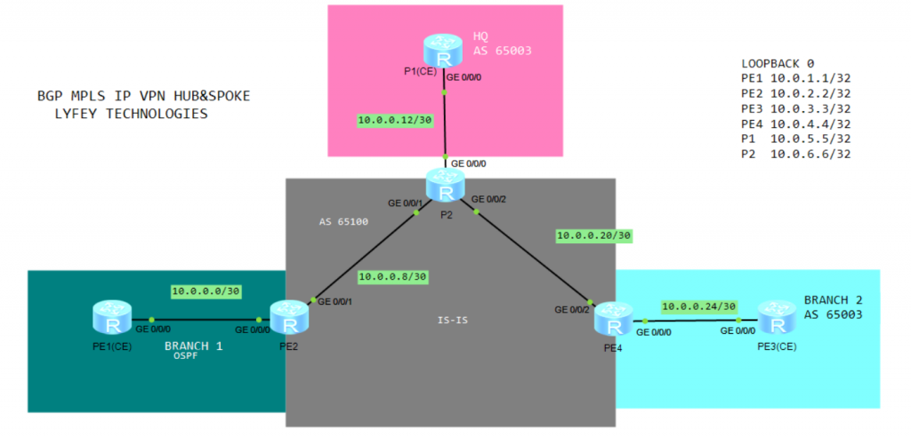
Topology
For this topology we have one Hub site(HQ) and two Branch sites (Spokes). The Branches and the HQ are connected via MPLS backbone network. For the Backbone network we run IS-IS as the IGP, BGP, MPLS and VPN. Branch 1 uses OSPF to connect to PE2, Branch 2 and HQ sites connects to PE via eBGP.
Configuration Steps
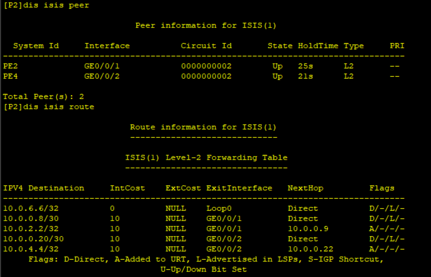
Step 1 Basic configuration of device IP addresses, IS-IS and MPLS for the Backbone network
***********************************PE2
system-view
sysname PE2
#
mpls lsr-id 10.0.2.2
mpls
#
mpls ldp
#
isis 1
 is-level level-2
 cost-style wide
 network-entity 49.0001.0000.0000.0002.00
 is-name PE2
#
interface GigabitEthernet0/0/1
 ip address 10.0.0.9 255.255.255.252
 isis enable 1
 isis circuit-type p2p
 mpls
 mpls ldp
#
interface LoopBack0
 ip address 10.0.2.2 255.255.255.255
 isis enable 1
#
***********************************P2
system-view
sysname P2
#
mpls lsr-id 10.0.6.6
mpls
#
mpls ldp
#
isis 1
is-level level-2
cost-style wide
network-entity 49.0001.0000.0000.0006.00
is-name P2
#
interface GigabitEthernet0/0/1
ip address 10.0.0.10 255.255.255.252
isis enable 1
isis circuit-type p2p
mpls
mpls ldp
interface GigabitEthernet0/0/2
ip address 10.0.0.21 255.255.255.252
isis enable 1
isis circuit-type p2p
mpls
mpls ldp
#
#
interface LoopBack0
ip address 10.0.6.6 255.255.255.255
isis enable 1
#***********************************PE4
system-view
sysname PE4
#
mpls lsr-id 10.0.4.4
mpls
#
mpls ldp
#
isis 1
is-level level-2
cost-style wide
network-entity 49.0001.0000.0000.0004.00
is-name PE4
#
interface GigabitEthernet0/0/2
ip address 10.0.0.22 255.255.255.252
isis enable 1
isis circuit-type p2p
mpls
mpls ldp
#
interface LoopBack0
ip address 10.0.4.4 255.255.255.255
isis enable 1
#Verify ISIS status
Step 2 Create VPNs on PEs and bind the VPNs to the relevant interfaces and assign IP addresses to interfaces facing the CEs
***********************************PE2
ip vpn-instance vpna
 ipv4-family
  route-distinguisher 10:20
  apply-label per-instance
  vpn-target 10:26 export-extcommunity
  vpn-target 10:624 import-extcommunity
#
interface GigabitEthernet0/0/0
 ip binding vpn-instance vpna
 ip address 10.0.0.2 255.255.255.252

#
On P2 we create VPN instance vpna_in to receive routes and VPN instance vpna_out to send routes. This is used to implement Spokes communication via HQ
***********************************P2
ip vpn-instance vpna_in
 ipv4-family
  route-distinguisher 10:60
  vpn-target 10:46 10:26 import-extcommunity
#
ip vpn-instance vpna_out
 ipv4-family
  route-distinguisher 10:6060
  vpn-target 10:624 export-extcommunity
#
interface GigabitEthernet0/0/0
 ip binding vpn-instance vpna_out
 ip address 10.0.0.14 255.255.255.252
#
interface GigabitEthernet0/0/0.1
 vlan-type dot1q 10
 ip binding vpn-instance vpna_in
 ip address 10.0.0.114 255.255.255.252
***********************************PE4
ip vpn-instance vpna
ipv4-family
route-distinguisher 10:40
vpn-target 10:46 export-extcommunity
vpn-target 10:624 import-extcommunity
#
interface GigabitEthernet0/0/0
ip binding vpn-instance vpna
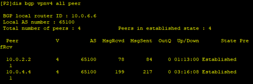
ip address 10.0.0.26 255.255.255.252Step 3 Configure iBGP between Backbone routers. BGP is used to advertise VPNv4 routes between the PEs . P2 is configured as our RR to reflect routes between PE2 and PE4.
***********************************PE2
 bgp 65100
 router-id 10.0.2.2
 peer 10.0.6.6 as-number 65100
 peer 10.0.6.6 connect-interface LoopBack0
 #
 ipv4-family unicast
  undo synchronization
  undo peer 10.0.6.6 enable
 #
 ipv4-family vpnv4
  policy vpn-target
  peer 10.0.6.6 enable
***********************************P2
bgp 65100
router-id 10.0.6.6
peer 10.0.2.2 as-number 65100
peer 10.0.2.2 connect-interface LoopBack0
peer 10.0.4.4 as-number 65100
peer 10.0.4.4 connect-interface LoopBack0
#
ipv4-family unicast
undo synchronization
undo peer 10.0.2.2 enable
undo peer 10.0.4.4 enable
#
ipv4-family vpnv4
undo policy vpn-target
peer 10.0.2.2 enable
peer 10.0.2.2 reflect-client
peer 10.0.4.4 enable
peer 10.0.4.4 reflect-client
***********************************PE4
bgp 65100
 router-id 10.0.4.4
 peer 10.0.6.6 as-number 65100
 peer 10.0.6.6 connect-interface LoopBack0
 #
 ipv4-family unicast
  undo synchronization
  peer 10.0.6.6 enable
 #
 ipv4-family vpnv4
  policy vpn-target
  peer 10.0.6.6 enable
Verify BGP peering
Step 4 Configure OSPF between PE2 and Branch 1 router (PE1) and create loopback 1 at the Branch to simulate a service/user
***********************************PE1
ospf 1 router-id 10.0.1.1
 area 0.0.0.0
#
interface GigabitEthernet0/0/0
 ip address 10.0.0.1 255.255.255.252
 ospf enable 1 area 0.0.0.0
#
interface LoopBack0
 ip address 10.0.1.1 255.255.255.255
#
#interface LoopBack1
 ip address 10.1.1.1 255.255.255.255
 ospf enable 1 area 0.0.0.0
#interface GigabitEthernet0/0/0
 ip address 10.0.0.1 255.255.255.252
 ospf enable 1 area 0.0.0.0
***********************************PE2
ospf 1 router-id 10.0.2.2 vpn-instance vpna
import-route bgp cost 20 type 2
area 0.0.0.0
#
interface GigabitEthernet0/0/0
ip binding vpn-instance vpna
ip address 10.0.0.2 255.255.255.252
ospf enable 1 area 0.0.0.0
#
ip ip-prefix loopback1 index 10 permit 10.1.1.1 32
#
route-policy IMPORT_OSPF_T0_BGP permit node 10
if-match ip-prefix loopback1
#
bgp 65100
ipv4-family vpn-instance vpna
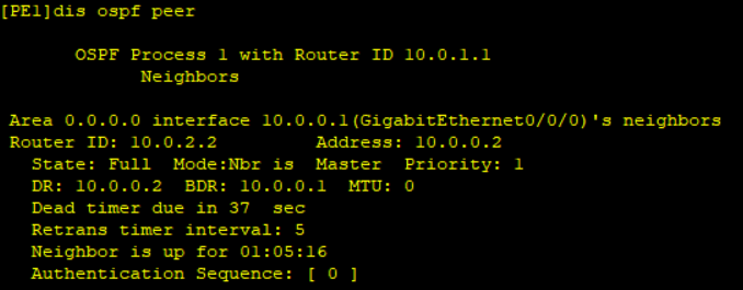
import-route ospf 1 route-policy IMPORT_OSPF_T0_BGPVerify OSPF peering status
Step 5 Configure eBGP between HQ router and P2 and create loopback 1 at the HQ router to simulate a service/user
***********************************P1(HQ router)
interface LoopBack0
 ip address 10.0.5.5 255.255.255.255
#
interface LoopBack1
 ip address 10.1.5.5 255.255.255.255
#
interface GigabitEthernet0/0/0
 ip address 10.0.0.13 255.255.255.252
#
interface GigabitEthernet0/0/0.1
 vlan-type dot1q 10
 ip address 10.0.0.113 255.255.255.252
#
bgp 65003
 router-id 10.0.5.5
 peer 10.0.0.14 as-number 65100
 peer 10.0.0.114 as-number 65100
 #
 ipv4-family unicast
  undo synchronization
  network 10.0.0.0
  network 10.1.5.5 255.255.255.255
  peer 10.0.0.14 enable
  peer 10.0.0.114 enable
The AS path attribute of the BGP VPNv4 routes received in the VPN instance vpn_in carries AS 65003.P1 discards the route due to loop prevention mechanism. Therefore you need to configure substitute-as to substitute the AS number. The branch routes learned in vpna_in are advertised to the vpna_out instance in the form of BGP routes through the CE(P1) of the HQ. However, P2 does not learn the routes because they carry the local AS ID. Therefore, the allow-as-loop must be configured
***********************************P2
bgp 65100
ipv4-family vpn-instance vpna_in
  peer 10.0.0.113 as-number 65003
  peer 10.0.0.113 substitute-as
 #
 ipv4-family vpn-instance vpna_out
  peer 10.0.0.13 as-number 65003
  peer 10.0.0.13 allow-as-loop 2
Step 6 Configure eBGP betwen Branch 2 router(PE3) and P2 and create loopback 1 at the Branch router to simulate a service/user
***********************************PE3
interface LoopBack0
 ip address 10.0.3.3 255.255.255.255
#
interface LoopBack1
 ip address 10.1.3.3 255.255.255.255
#
interface GigabitEthernet0/0/0
 ip address 10.0.0.25 255.255.255.252
#
bgp 65003
 router-id 10.0.3.3
 peer 10.0.0.26 as-number 65100
 #
 ipv4-family unicast
  undo synchronization
  network 10.1.3.3 255.255.255.255
  peer 10.0.0.26 enable
***********************************PE4
bgp 65100
ipv4-family vpn-instance vpna
  peer 10.0.0.25 as-number 65003
  peer 10.0.0.25 substitute-as
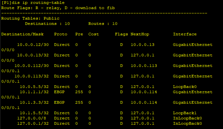
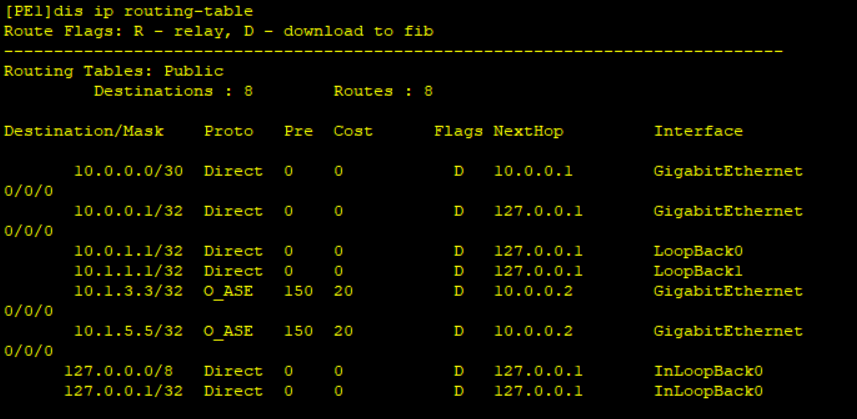
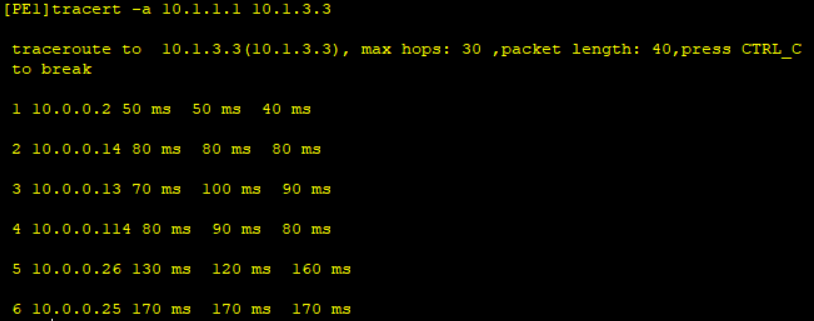
Step 7 Verify communication between the Branches

Leave a Reply
You must be logged in to post a comment.