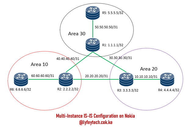
Basic IS-IS Multi-Area Configuration on Nokia Routers
- March 14, 2024
- Posted by: Lyfey Technologies
- Categories: Networking, Nokia

Topology description
As shown in the topology above, the network has six routers R1, R2, R3, R4, R5, and R6. There are three IS-IS areas 10, 20, and 30. R1, R2, and R3 and the backbone routers and configured as L1/L2 routers, they establish L2 adjacencies among them. R4, R5, and R6 are internal routers and they establish L1 adjacences with the connected backbone routers.
Configuration Step 1: Configure interfaces and IP addresses on the six routers.
***********************R1
/configure router
        interface "TO_R2"
            address 40.40.40.41/31
            description "TO_R2"
            port 1/x1/1/c1/1
            no shutdown
        exit
        interface "TO_R3"
            address 30.30.30.30/31
            description "TO_R1"
            port 1/x1/1/c2/1
            no shutdown
        exit
        interface "TO_R5"
            address 50.50.50.50/31
            description "TO_R5"
            port 1/x1/1/c3/1
            no shutdown
        exit
        interface "system"
            address 1.1.1.1/32
            no shutdown
        exit
****************************R2
/configure router
        interface "TO_R1"
            address 40.40.40.40/31
            description "TO_R3"
            port 1/x1/1/c1/1
            no shutdown
        exit
        interface "TO_R3"
            address 20.20.20.20/31
            description "TO_R3"
            port 1/x1/1/c2/1
            no shutdown
        exit
        interface "TO_R6"
            address 60.60.60.61/31
            description "TO_R6"
            port 1/x1/1/c3/1
            no shutdown
        exit
        interface "system"
            address 2.2.2.2/32
            no shutdown
        exit
*******************************R3
/configure router
interface "TO_R1"
address 30.30.30.31/31
description "TO_R1"
port 1/x1/1/c2/1
no shutdown
exit
interface "TO_R2"
address 20.20.20.21/31
description "TO_R2"
port 1/x1/1/c1/1
no shutdown
exit
interface "TO_R4"
address 10.10.10.10/31
description "TO_R4"
port 1/x1/1/c3/1
no shutdown
exit
interface "system"
address 3.3.3.3/32
no shutdown
exit
******************************R4
 /configure router
        interface "TO_R3"
            address 10.10.10.11/31
            description "TO_R3"
            port 1/x1/1/c1/1
            no shutdown
        exit
        interface "system"
            address 4.4.4.4/32
            no shutdown
        exit
*******************************R5
/configure router
interface "TO_R1"
address 50.50.50.51/31
description "TO_R1"
port 1/x1/1/c1/1
no shutdown
exit
interface "system"
address 5.5.5.5/32
no shutdown
exit
****************************R6
/configure router
        interface "TO_R2"
            address 60.60.60.60/31
            description "TO_R2"
            port 1/x1/1/c1/1
            no shutdown
        exit
        interface "system"
            address 6.6.6.6/32
            no shutdown
        exit
Configuration Step 2: Confirm you can ping P2P between different interfaces on different routers. We can ping R6, R1, and R3 from R2 as shown below

Configuration Step 3: Configure ISIS and enable IS-IS on all interfaces on the six routers as follows.
*******************************R1
/configure router
        isis 30
            router-id 1.1.1.1
            level-capability level-1/2
            area-id 49.0030
            interface "system"
                interface-type point-to-point
                no shutdown
            exit
            interface "TO_R5"
                level-capability level-1/2
                interface-type point-to-point
                level 2
                    metric 100
                exit
                no shutdown
            exit
            interface "TO_R2"
                level-capability level-2
                interface-type point-to-point
                level 2
                    metric 100
                exit
                no shutdown
            exit
            interface "TO_R3"
                level-capability level-2
                interface-type point-to-point
                level 2
                    metric 100
                exit
                no shutdown
            exit
            no shutdown
        exit
    exit
*****************************R2
/configure router
isis 10
router-id 2.2.2.2
level-capability level-1/2
area-id 49.0010
interface "system"
interface-type point-to-point
no shutdown
exit
interface "TO_R6"
level-capability level-1/2
interface-type point-to-point
level 2
metric 100
exit
no shutdown
exit
interface "TO_R3"
level-capability level-2
interface-type point-to-point
level 2
metric 100
exit
no shutdown
exit
interface "TO_R1"
level-capability level-2
interface-type point-to-point
level 2
metric 100
exit
no shutdown
exit
no shutdown
exit
exit*********************************R3
/configure router
isis 20
router-id 3.3.3.3
area-id 49.0020
level-capability level-1/2
interface "system"
interface-type point-to-point
no shutdown
exit
interface "TO_R1"
level-capability level-2
interface-type point-to-point
level 2
metric 100
exit
no shutdown
exit
interface "TO_R2"
level-capability level-2
interface-type point-to-point
level 2
metric 100
exit
no shutdown
exit
interface "TO_R4"
level-capability level-1/2
interface-type point-to-point
level 2
metric 100
exit
no shutdown
exit
no shutdown
exit
exit
**************************************R4
/configure router
        isis 20
            router-id 4.4.4.4
            level-capability level-1
            area-id 49.0020
            interface "system"
                interface-type point-to-point
                no shutdown
            exit
            interface "TO_R3"
                level-capability level-1
                interface-type point-to-point
                level 2
                    metric 100
                exit
                no shutdown
            exit
            no shutdown
        exit
    exit
*************************R5
/configure router
isis 30
router-id 5.5.5.5
level-capability level-1
area-id 49.0030
interface "system"
interface-type point-to-point
no shutdown
exit
interface "TO_R1"
level-capability level-1
interface-type point-to-point
level 2
metric 100
exit
no shutdown
exit
no shutdown
exit
exit**************************************R6
/configure router
isis 10
router-id 6.6.6.6
level-capability level-1
area-id 49.0010
interface "system"
interface-type point-to-point
no shutdown
exit
interface "TO_R2"
level-capability level-1
interface-type point-to-point
level 2
metric 100
exit
no shutdown
exit
no shutdown
exit
exitConfiguration Step 4: Verify IS-IS status and confirm reachability among different IS-IS areas.

We can see detailed information about the adjacency by running the command ” show router isis 10 adjacency detail“.

We have learned IS-IS routes on R3 as shown below

We can ping the system IPs of R4 and R6 from R5.

Leave a Reply
You must be logged in to post a comment.
