BGP(Border Gateway Protocol) is a very common protocol used in Carrier and Enterprise networks due to its scalability and flexibility features. In this article, we will focus on how to configure the basic functions of BGP on Huawei Routers.
As shown in the diagram above, We have two ASes 100 and 200. OSPF is configured as the IGP in AS 100 and IS-IS is configured as the IGP in AS 200. We configure IBGP in each AS and EBGP between the two ASes.
Configuration Steps:
Step 1: Configure IP address on physical and logical interfaces on all the routers in each AS.
******************************R1
sys
interface LoopBack0
 ip address 1.1.1.1 255.255.255.255
#
interface GigabitEthernet0/0/0
 description TO_R3_GE0/0/0
 ip address 10.10.10.2 255.255.255.254
#
interface GigabitEthernet0/0/1
 description TO_R2_GE0/0/0
 ip address 10.10.10.0 255.255.255.254
#
interface GigabitEthernet0/0/2
 description TO_R4_GE0/0/2
 ip address 30.30.30.0 255.255.255.254
#
*********************************R2
sys
interface LoopBack0
ip address 2.2.2.2 255.255.255.255
#
#
interface GigabitEthernet0/0/0
description TO_R1_GE0/0/1
ip address 10.10.10.1 255.255.255.254
#
commit**********************************R3
sys
interface LoopBack0
ip address 3.3.3.3 255.255.255.255
#
interface GigabitEthernet0/0/0
description TO_R1_GE0/0/0
ip address 10.10.10.3 255.255.255.254
#
commit******************************R4
sys
#
interface LoopBack0
ip address 4.4.4.4 255.255.255.255
#
interface GigabitEthernet0/0/0
description TO_R6_GE0/0/0
ip address 20.20.20.2 255.255.255.254
isis enable 10
#
interface GigabitEthernet0/0/1
description TO_R5_GE0/0/1
ip address 20.20.20.0 255.255.255.254
isis enable 10
#
interface GigabitEthernet0/0/2
description TO_R1_GE0/0/2
ip address 30.30.30.1 255.255.255.254
#
commit*******************************R5
sys
interface LoopBack0
ip address 5.5.5.5 255.255.255.255
#
interface GigabitEthernet0/0/0
description TO_R6_GE0/0/0
ip address 20.20.20.1 255.255.255.254
isis enable 10
#
interface GigabitEthernet0/0/1
description TO_R4_GE0/0/1
ip address 20.20.20.4 255.255.255.254
isis enable 10
#
commit*******************************R6
sys
interface LoopBack0
ip address 6.6.6.6 255.255.255.255
#
interface GigabitEthernet0/0/0
description TO_R4_GE0/0/0
ip address 20.20.20.3 255.255.255.254
isis enable 10
#
interface GigabitEthernet0/0/1
description TO_R5_GE0/0/1
ip address 20.20.20.5 255.255.255.254
isis enable 10
#
commitStep 2: Configure IGP on each router in the two ASes and enable IGP on Loopback 0 and physical interfaces within the AS.
***************R1

#
ospf 10 router-id 1.1.1.1
 area 0.0.0.0
  network 10.10.10.0 0.0.0.1
  network 10.10.10.2 0.0.0.1
  network 1.1.1.1 0.0.0.0
#
*******************R2
#
ospf 10 router-id 2.2.2.2
area 0.0.0.0
network 2.2.2.2 0.0.0.0
network 10.10.10.0 0.0.0.1
#******************R3
#
ospf 10 router-id 3.3.3.3
area 0.0.0.0
network 3.3.3.3 0.0.0.0
network 10.10.10.2 0.0.0.1
#
commit******************R4
isis 10
is-level level-2
cost-style wide
network-entity 49.0010.0004.0004.0004.00
is-name R4
#
interface Loopback 0
isis enable 10
interface GigabitEthernet0/0/0
isis enable 10
#
interface GigabitEthernet0/0/1
isis enable 10
#
commit******************R5
isis 10
is-level level-2
cost-style wide
network-entity 49.0010.0005.0005.0005.00
is-name R5
#
interface Loopback 0
isis enable 10
interface GigabitEthernet0/0/0
isis enable 10
#
interface GigabitEthernet0/0/1
isis enable 10
#
commit*************************R6
#
isis 10
is-level level-2
cost-style wide
network-entity 49.0010.0006.0006.0006.00
is-name R6
#
interface Loopback 0
isis enable 10
interface GigabitEthernet0/0/0
isis enable 10
#
interface GigabitEthernet0/0/1
isis enable 10
#
commitStep 3: Configure BGP on all the routers in the two ASes.
************************R1********************
#
bgp 100
 router-id 1.1.1.1
 peer 2.2.2.2 as-number 100
 peer 2.2.2.2 connect-interface LoopBack0
 peer 3.3.3.3 as-number 100
 peer 3.3.3.3 connect-interface LoopBack0
 peer 30.30.30.1 as-number 200
 #
 ipv4-family unicast
  undo synchronization
  peer 2.2.2.2 enable
  peer 3.3.3.3 enable
  peer 30.30.30.1 enable
#
commit
***************************R2**************************
#
bgp 100
router-id 2.2.2.2
peer 1.1.1.1 as-number 100
peer 1.1.1.1 connect-interface LoopBack0
#
ipv4-family unicast
undo synchronization
peer 1.1.1.1 enable
#
commit*************************R3********************************
#
bgp 100
router-id 3.3.3.3
peer 1.1.1.1 as-number 100
peer 1.1.1.1 connect-interface LoopBack0
#
ipv4-family unicast
undo synchronization
peer 1.1.1.1 enable
#
commit**************************R4******************************
#
bgp 200
router-id 4.4.4.4
peer 5.5.5.5 as-number 200
peer 5.5.5.5 connect-interface LoopBack0
peer 6.6.6.6 as-number 200
peer 6.6.6.6 connect-interface LoopBack0
peer 30.30.30.0 as-number 100
#
ipv4-family unicast
undo synchronization
peer 5.5.5.5 enable
peer 6.6.6.6 enable
peer 30.30.30.0 enable
#
commit**************************************R5********************************
bgp 200
router-id 5.5.5.5
peer 4.4.4.4 as-number 200
peer 4.4.4.4 connect-interface LoopBack0
peer 6.6.6.6 as-number 200
peer 6.6.6.6 connect-interface LoopBack0
#
ipv4-family unicast
undo synchronization
peer 4.4.4.4 enable
peer 6.6.6.6 enable
#
commit*******************************R6*******************************
#
bgp 200
router-id 6.6.6.6
peer 4.4.4.4 as-number 200
peer 4.4.4.4 connect-interface LoopBack0
peer 5.5.5.5 as-number 200
peer 5.5.5.5 connect-interface LoopBack0
#
ipv4-family unicast
undo synchronization
peer 4.4.4.4 enable
peer 5.5.5.5 enable
#
commitStep 4: Verification
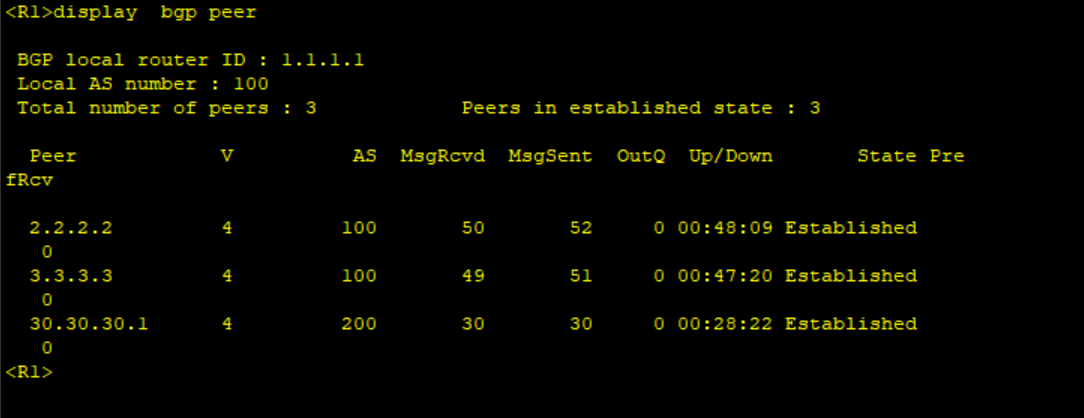
Run display bgp peer on the routers to check BGP status.
Create Loopback 100 on R2 and advertise it under BGP, Loopack 100 is not advertised in OSPF. Check the route on R1 using the command “display bgp routing-table“.
********************R2
interface Loopback 100
ip address 100.100.100.100 32
#
bgp 100
network 100.100.100.100 255.255.255.255
#
commit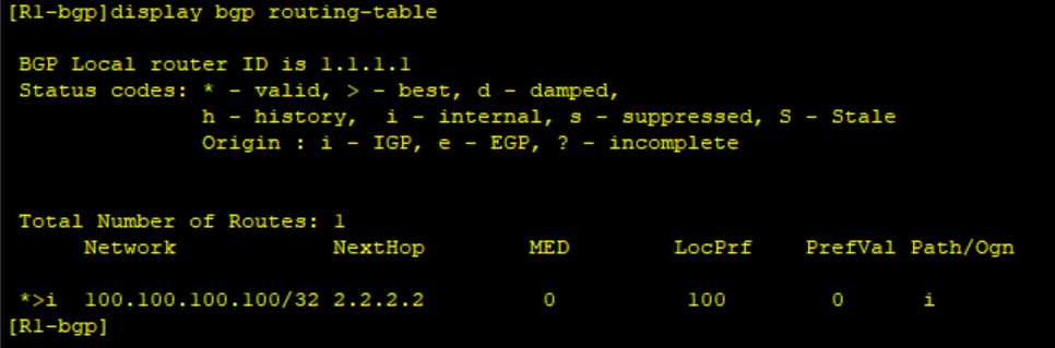
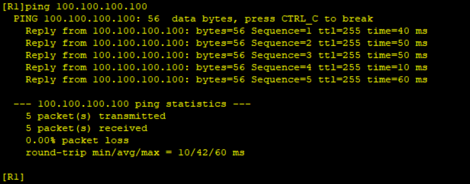
Do a ping from R1 to 100.100.1001.00. As shown below, we can ping Loopback 100 IP from R4.
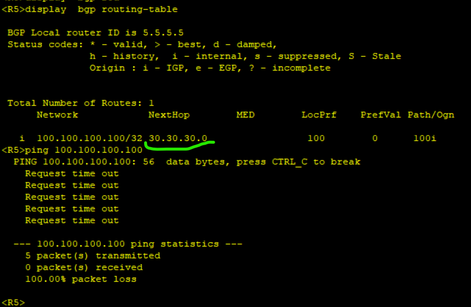
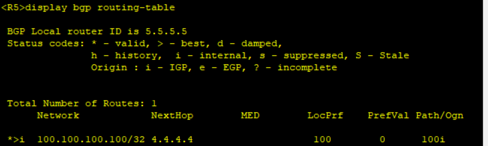
Check the routing table of R5 and do a ping to Loopback 100 of R2.
To fix the above issue, you need to configure R4 to advertise BGP routes using itself as the next hop. Run below commands on R4.
********************R4
#
bgp 200
peer 5.5.5.5 next-hop-local
peer 6.6.6.6 next-hop-local
#
commit
Recheck the routing table of R5 and now the next hop is Loopback 0 of R4.
Lab setup and configuration are available on demand. Leave your questions in the comment section.